Yaskawa CM091 User Manual
Page 5
Yaskawa Electric America, Inc –
www.yaskawa.com
IG.V7.25, Page 5 of 6
Date: 10/08/09, Rev: 09-10
16.
Remove power from the V7 drive and wait for the charge lamp to be
completely extinguished. Wait at least five additional minutes for the V7
to be completely discharged. Measure the DC bus voltage and verify
that it is at a safe level.
17.
Reinstall the operator keypad and terminal cover.
18.
Reapply power to the V7 drive.
19.
Set parameters n003 and n004 to their appropriate values.
Important Notes:
1. Note: A maximum of 10 simultaneous connections are allowed.
2. The Run Command and Frequency Reference may only be accessed
through UNIT ID 1. While the V7 drive is in remote Run mode, the
Run command must be continually refreshed within the configured
EF0 timeout value. If the Run command is not refreshed within the set
timeout period, an EF0 fault will occur. Refer to the appropriate V7
manual for information on EF0 and setting the appropriate V7
response. If a UNIT ID 1 connection is active, the NS/CON LED will
blink at approximately a 500ms cycle.
3. The TCP/IP connection must be refreshed within 60 seconds. If it is
not refreshed within 60 seconds, the connection will be closed.
4. This implementation of Modbus TCP/IP supports the following Modbus functions: 3 (read multiple registers), 6 (write single register), 16 (write multiple registers) and
23 (read/write multiple registers).
5. Refer to the appropriate programming or parameter access manual for a complete list of V7 parameters and registers available. A list of applicable manuals is available
at the end of this document.
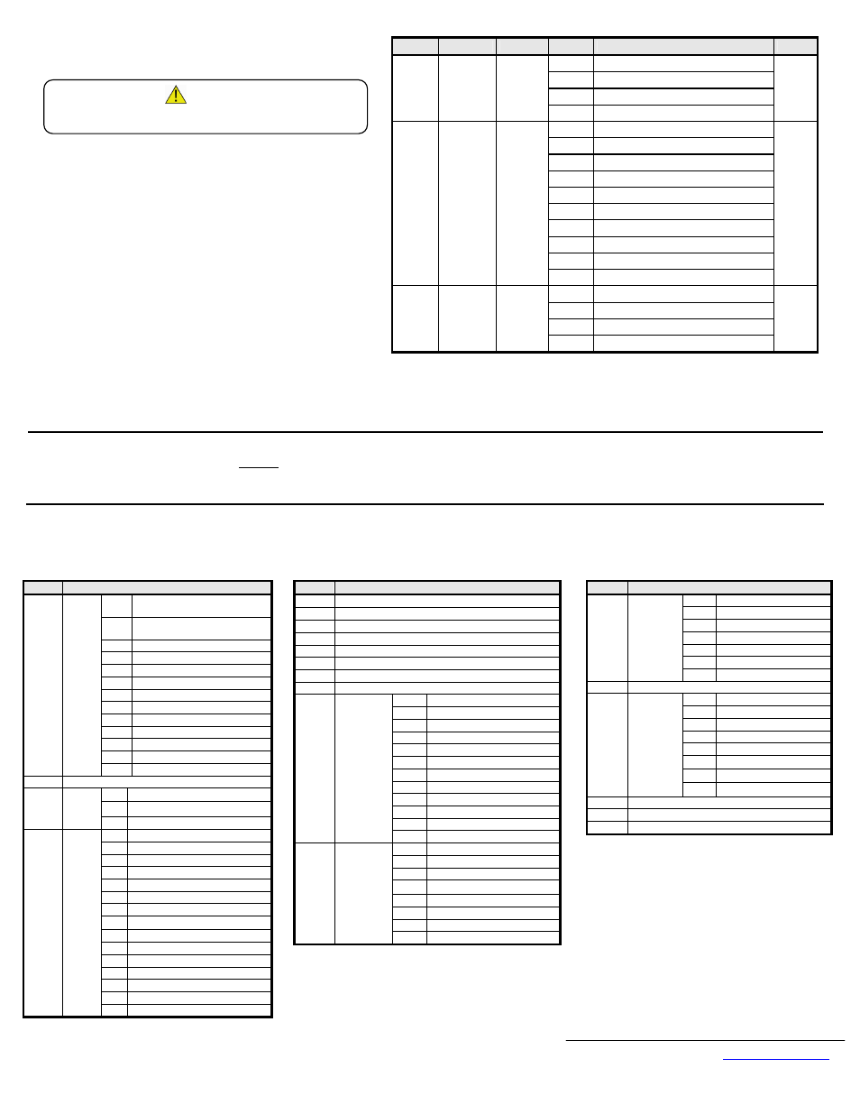
Address Parameter Function
Data
Description
Default
0 Operator
Keypad
1 Terminal
Strip
2
Built-in Modbus RTU
103h n003
Operation
Method
Selection
3
Option Kit (V7 Modbus TCP/IP Option)
1
0
Operator Keypad Potentiometer
1
Operator Keypad
2
Voltage Reference (0-10VDC)
3
Current Reference (4-20mA)
4
Current Reference (0-20mA)
5
Pulse Train Reference
6
Built-in Modbus RTU
7
Multi-Function Analog Input (0-10VDC)
8
Multi-Function Analog Input (4-20mA)
104h n004
Reference
Selection
9
Option Kit (V7 Modbus TCP/IP Option)
2
0 0.01
Hz
1 0.1
%
2-39
RPM (Enter motor poles)
198h n152
Display
Scaling
40-3999 User
Setting
0
20.
Notes:
1.
It is strongly recommended that shielded CAT-5 cable be used. Verify that the shield is continuous to the drive and that it is grounded only at the drive end.
2.
DriveWizard version 6.1 or later with a custom database is required for DriveWizard to operate with this option. Install DriveWizard with the
“Custom” install option checked and the appropriate databases selected.
21. Registers Available via High-Speed Command Registers
Command Register access is designed to be used as part of the standard PLC I/O or scan table, where fast response is required. Other register values should be accessed via
individual messages, i.e. via an MSTR block. Addresses 0001h, 0002h and 0009h may be written while all other registers in the table below are read only. Addresses 0001h and
0002h may only be accessed through Unit ID 1 (see above). Please note that Modbus RTU has different command registers.
Address
Description
0h
Multi-Function Digital Input S1
(Forward Run)
1h
Multi-Function Digital Input S2
(Reverse Run)
2h
Multi-Function Digital Input S3
3h
Multi-Function Digital Input S4
4h
Multi-Function Digital Input S5
5h
Multi-Function Digital Input S6
6h
Multi-Function Digital Input S7
7h Reserved
8h
External Fault (EF0)
9h Fault
Reset
Ah-Dh Reserved
Eh
Fault Log Trace Clear
0001h
Digital
Input
Command
Fh External
Base
Block
0002h
Frequency Reference Command (Scaled by n152)
0h Terminals MA, MB, MC
1h Terminals P1, PC
0009h
Digital
Output
Command
2h Terminals P2, PC
0h During
Run
1h Zero
Speed
2h Reverse
Direction
3h During
Fault
Reset
4h Speed
Agree
5h Drive
Ready
6h Minor Fault (Alarm)
7h Major
Fault
8h OPE
Fault
9h Momentary Powerloss Ride Thru
Ah Local
Mode
Bh Digital Output Terminals MA, MB, MC
Ch Digital Output Terminals P1, PC
Dh Digital Output Terminals P2, PC
2000h
Status
Word
Eh-Fh Reserved
Address
Description
2001h
Output Frequency (U-02) (Scaled by n152)
2002h
Torque Monitor (U-08) (1%) (Open Loop Vector only)
2003h Reserved
2004h
Frequency Reference Monitor (U-02) (Scaled by n152)
2005h
Output Frequency (U-02) (Scaled by n152)
2006h
Output Current (U-03) (0.1A)
2007h
Pulse Input (Terminal RP) Value
2008h
DC Bus Voltage (U-05) (1VDC)
0h Reserved
1h
UV1 Main Circuit Undervoltage
2h
UV2 Control Power Undervoltage
3h Reserved
6h OC
Overcurrent
7h OV
Overvoltage
8h OH
Overheat
9h Reserved
Ah
OL1 Motor Overload
Bh OL2
Drive
Overload
Ch OL3
Overtorque
Detection
2009h
Error Signal 1
Dh-Fh Reserved
0h
EF3 External Fault S3
1h
EF4 External Fault S4
2h
EF5 External Fault S5
3h
EF6 External Fault S6
4h
EF7 External Fault S7
5h ~ Ch Reserved
Dh
oPA Operator Disconnected
200Ah
Error Signal 2
Eh ~ Fh Reserved
Address
Description
0h
CE Communications Fault
1h
BUS Option Error
2h ~ 5h Reserved
6h
EF0 Option External Error
8h UL3
Undertorque
Detection
9h ~ Eh Reserved
200Bh
Error Signal 3
Fh
Fxx Hardware Fault
200Ch Reserved
0h Terminal
S1
1h Terminal
S2
2h Terminal
S3
3h Terminal
S4
4h Terminal
S5
5h Terminal
S6
6h Terminal
S7
200Dh
Digital Input
Terminal
Status
7h ~ Fh Reserved
200Eh Analog Input (Terminal FR) Value (0.1VDC)
200Fh Reserved
2010h
Drive Software Number (U-10)
WARNING!
Dangerous voltages in excess of 400VDC (230V drives) or 800VDC
(460V drives) are present at the DC bus terminals of the drive.