Yaskawa PG-X2 User Manual
Encoder feedback option card pg-x2
Yaskawa Electric America, Inc. – www.drives.com
IG.AFD.60, Page 1 of 8
Date: 07/01/04, Rev:04-07
Encoder Feedback Option Card
PG-X2
1. Part Number: PG-X2.
2. Applicability: F7, G7, GPD515/G5, G5HHP.
3. Introduction: The PG-X2 encoder feedback option card (Figure 1) is mounted on the drive’s Control Board and performs
speed feedback using the pulse generator (PG) on the motor to correct speed fluctuation caused by motor slip. Motor rotation
direction is detected by phase A and phase B PG pulse inputs. The terms encoder, PG (pulse generator), and pulse train are
used interchangeably in this guide. The card can be used for flux vector control or V/Hz with PG feedback control.
4. Receiving: All equipment is tested against defect at the factory. Report any damages or shortages evident when the
equipment is received to the commercial carrier who transported the equipment.
5. Cautions:
a. Hazardous voltage can cause severe injury or death. Lock all power sources feeding the drive in the “OFF” position.
b. This option card uses CMOS IC chips. Use proper electrostatic discharge (ESD) protective procedures when
handling the card to prevent I.C. damage or erratic drive operation.
c.
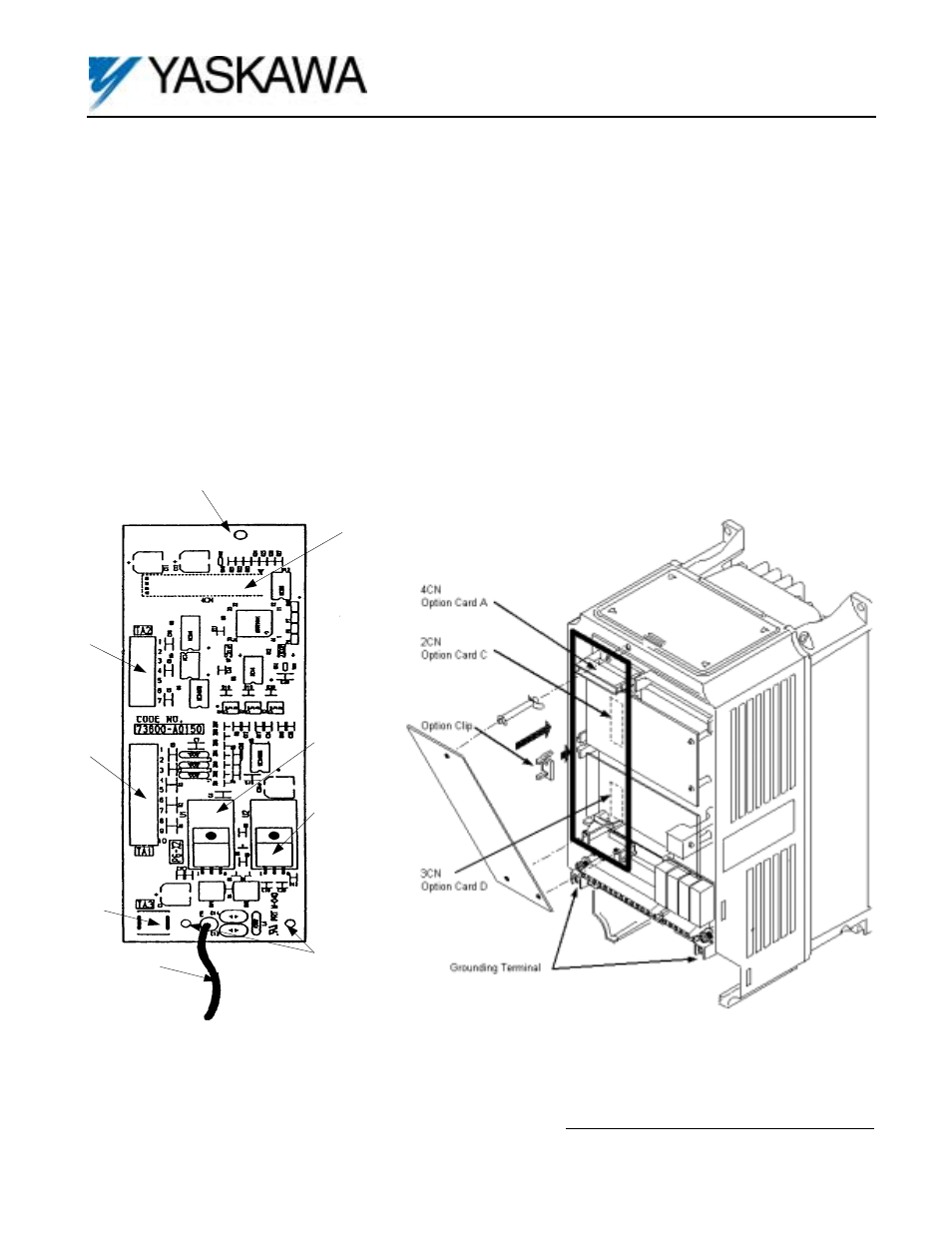
If other option cards are to be installed at the Option C (2CN) or Option D (3CN) positions (See Figure 2), their
installation and wiring should be completed before installation of this option.
d. Before installing this option, a technically qualified individual, who is familiar with this type of equipment and the
hazards involved, should read this entire installation guide.
Figure 1. PG-X2 Encoder Feedback Card
Figure 2. PG-X2 Option Card installation
Mounting Hole
Connector, Rear
Side of Board to
Control Bd., 4CN
Terminal
Block TA2
Terminal
Block TA1
Variable Resistor,
Adjusts
+12V PG Power
Variable Resistor,
Adjusts
+5V PG Power
Terminal TA3
Connect Shield
Here
2 Mounting Holes
Ground Lead Wire-
Connects to Grounding
Terminal on Control Board