Yaskawa DI-16H2 User Manual
Digital input option card di-16h2
Yaskawa Electric America, Inc. – www.drives.com
IG.AFD.59, Page 1 of 4
Date: 07/01/04, Rev: 04-07
Digital Input Option Card
DI-16H2
Part Number: DI-16H2.
Applicability: F7, G7, GPD515/G5, G5 HHP.
Introduction: The DI-16H2 digital input option card (Figure 2)
is mounted on the drive’s control board and allows the user to
interface a 12-bit or 16-bit digital speed reference to the drive.
This reference can be binary, binary coded decimal (BCD) in
hertz (Hz), or BCD in percent (%). Sign (polarity) and Set
(load) inputs are also included.
Receiving: All equipment is tested against defect at the
factory. Report any damages or shortages evident when the
equipment is received to the commercial carrier who
transported the equipment.
Warning: Hazardous voltage can cause severe injury or
death. Lock all power sources feeding the drive in the “OFF”
position.
Caution: This option card uses CMOS IC chips. Use proper
electrostatic discharge (ESD) protective procedures when
handling the card to prevent I.C. damage or erratic drive
operation.
Important:
a) If this option card is being installed in a drive with an
encoder (PG) feedback option card, that card will
need to be to temporarily removed to allow access to
connector 2CN on the drive’s control board and TC1-TC3 on
the DI-16H2 option card.
b) Before installing this option, a technically qualified individual,
who is familiar with this type of equipment and the hazards
involved, should read this entire installation guide.
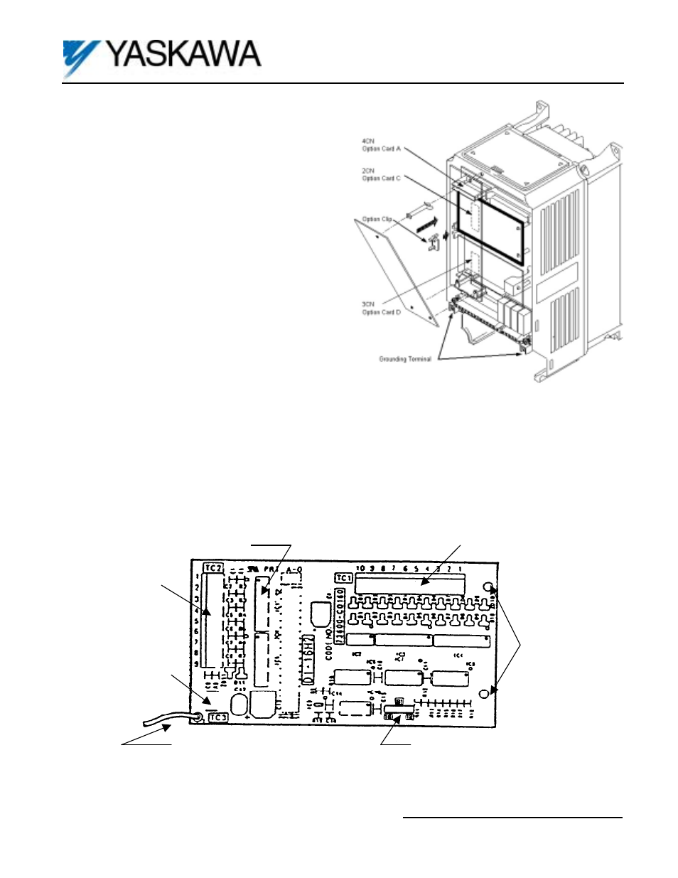
2 mounting
holes
Switch S1
(Selects 12 or 16 bit data)
Grounding Lead Wire (E) to drive Ground
Terminal: F7, G7 = TB3, GPD515/G5 = 12
Terminal TC3
(connect shield
sheath here)
Terminal Block
TC2
Terminal Block TC1
Connector, on reverse side to Control
Board 2CN
Figure 2. Digital Input Card DI-16H2
Figure 1. DI-16H2 Option Card Installation