Digital input option card di-08 – Yaskawa DI-08 User Manual
Page 2
Yaskawa Electric America, Inc. – www.drives.com
IG.AFD.58, Page 2 of 3
Date: 07/01/04, Rev: 04-07
Digital Input Option Card
DI-08
7. Adjustment: There are no adjustments that need to be made to the DI-08 option; however, the drive will have to be
programmed for the input requirements of the peripheral device. See Table 4.
Important: For the digital reference to function properly, the drive needs to be programmed to use the digital
reference. This can be done in one of two ways:
a) If drive always uses the DI-08 speed reference:
Program b1-01 = “3” (Option PCB)
b) If the drive is using multi-function digital inputs to select multiple speed references:
1. Program b1-01 = “0”, “1”, or “2” (depends on required speed reference source).
2. H1-03 (or other input) = “2” (Option / Inverter Select).
3. Close terminal S5 (5 on the G5) on the drive’s control board to select the DI-08 digital reference.
8. Reinstall and secure the drive’s cover.
9. Place this instruction sheet with the drive’s technical manual.
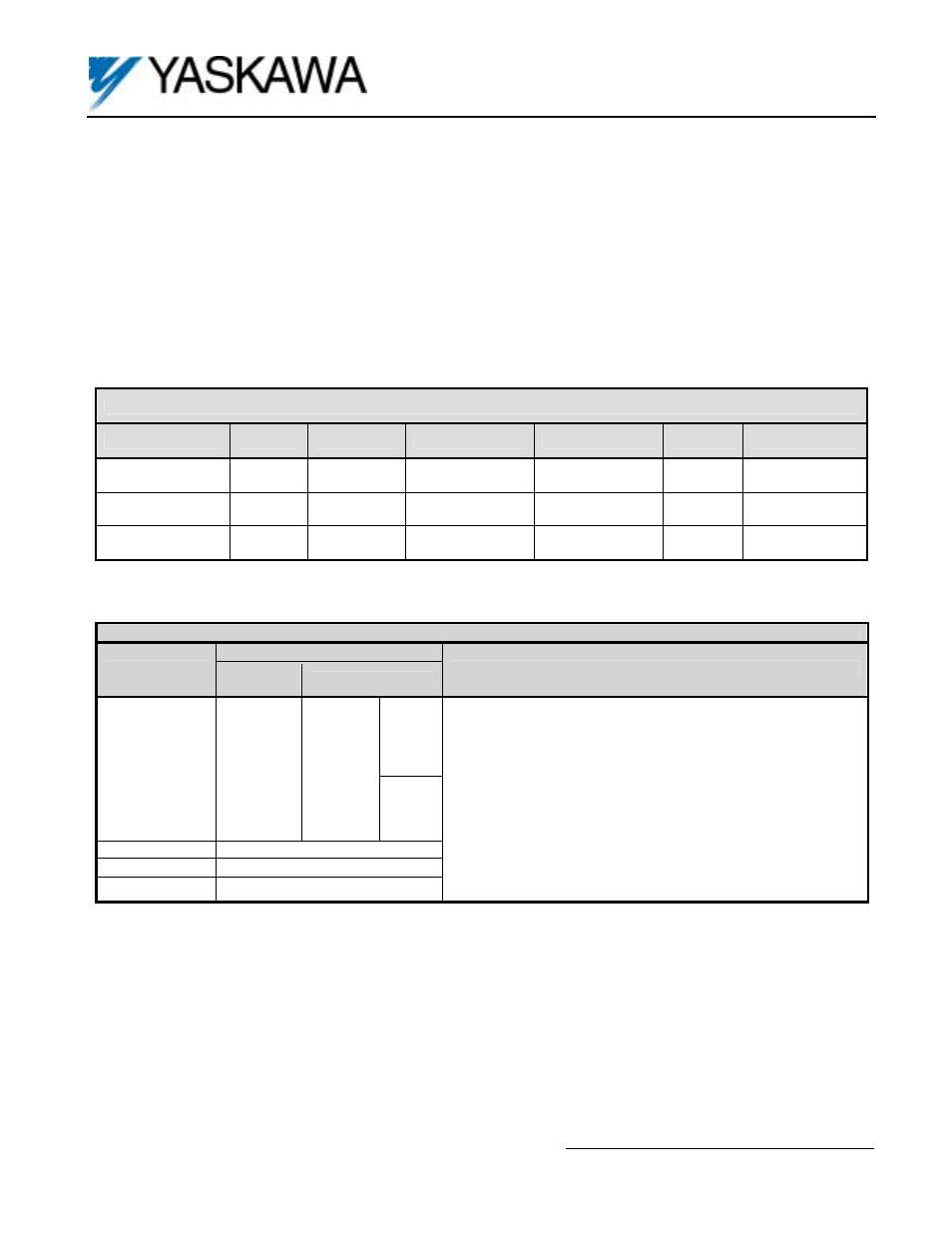
Table 1. DI-08 Specifications
Parameter
Symbol
Minimum
Typical
Maximum
Units
Test Conditions
High Level
Voltage Input
V
IH
12.5
24.0
VDC
R
L >
8.9K ohms
Low Level
Voltage Input
V
IL
0
12.0
VDC
R
L <
8.8K ohms
Logic Low
Current
6.4
10 mA
Table 2. Terminal Functions of the DI-08
Function
Terminal
Binary
Input
BCD Input
Notes
TC1 2
0
1
TC2 2
1
2
TC3 2
2
4
TC4 2
3
8
X 10
0
--- “On” when closed (shorted to 0VDC at TC11)
“Off” when open.
TC5 2
4
1
TC6 2
5
2
TC7 2
6
4
TC8 2
7
8
X 10
1
--- Binary / BCD selection and input unit is set by drive parameter
F3-01; see Table 4.
--- Terminal screws are metric M3.
TC9
SIGN (polarity) signal
TC10
SET (load) *
TC11
Signal Common (0V)
--- SIGN signal: “Off” = Forward Direction Command
: “On” = Reverse Direction Command
* SET (load) signal is used to tell the drive to read the data. To set, close between TC-10 and TC-11 by the timing shown
in Figure 3.