Isolated analog output option card ao-001 – Yaskawa AO-001 User Manual
Page 3
Yaskawa Electric America, Inc. – www.drives.com
IG.AFD.52, Page 3 of 5
Date: 11/03/04, Rev: 04-11
Isolated Analog Output Option Card
AO-001
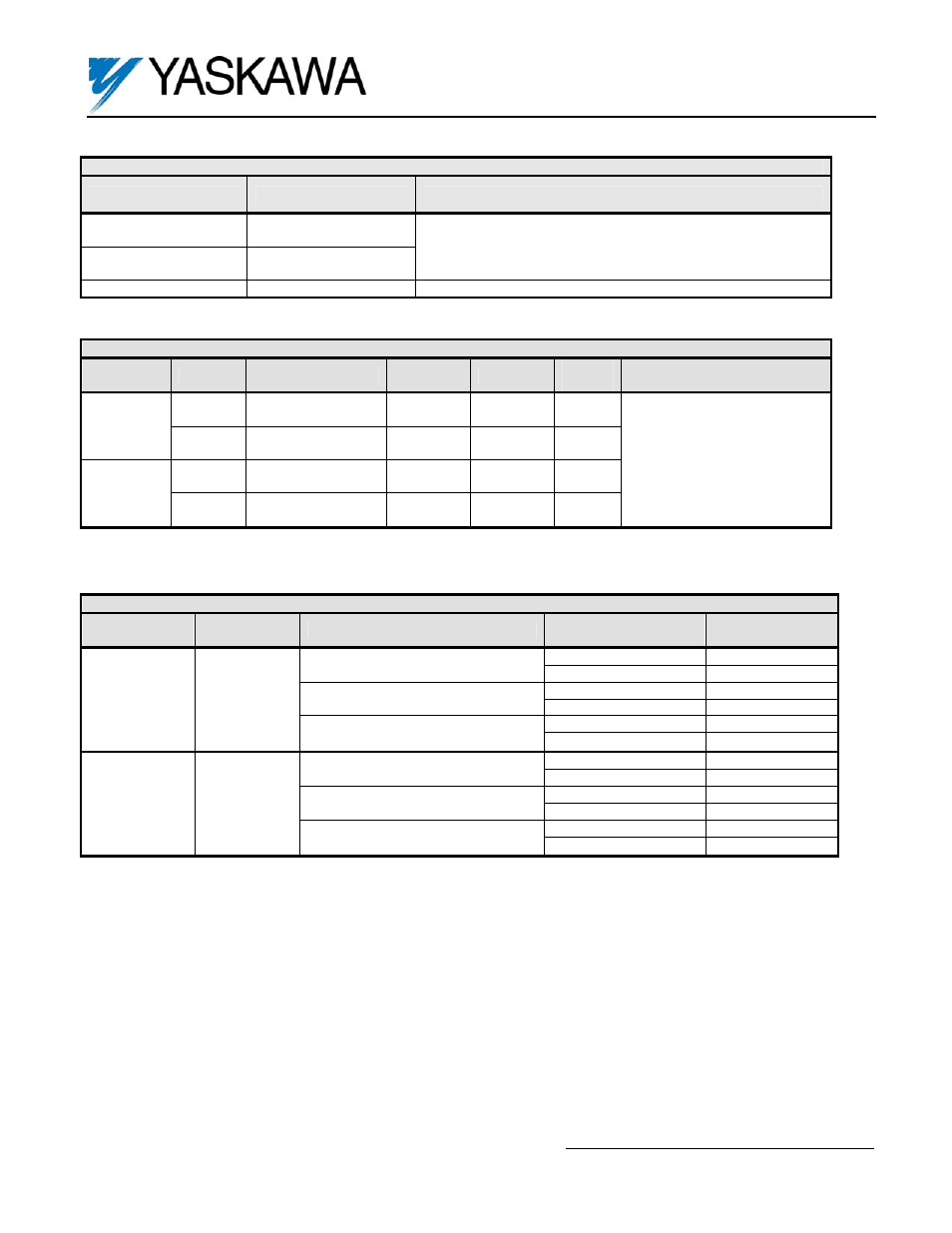
Table 2. Terminal Functions of the AO-001
Terminal
Functions
Signal Level
TB1-1
Analog Signal
Output Channel 1
TB1-2
Analog Signal
Output Channel 2
4-20mA, 0-20mA, 0-10VDC or +/- 10VDC
(1)
TB1-3 Output
Common
0V
(1) See step 7 above and tables 3 and 4 below for instructions on changing the signal type.
Table 4. Output Signal Type Configuration
Channel
TB1
Terminals
Signal Type
Jumper
Positions
HDR2
3-5 & 4-6
Current (4-20mA)
(1)
HDR4
1-3 & 4-6
1 (+)
HDR2
3-5 & 4-6
Current (0-20mA)
HDR4
3-4 & 5-6
HDR2
1-3 & 2-4
1
3 (-)
Voltage (0-10VDC or +/- 10VDC)
(2)
HDR4
1-3 & 4-6
HDR1
3-5 & 4-6
Current (4-20mA)
(1)
HDR3
1-3 & 4-6
2 (+)
HDR1
3-5 & 4-6
Current (0-20mA)
HDR3
3-4 & 5-6
HDR1
1-3 & 2-4
2
3 (-)
Voltage (0-10VDC or +/- 10VDC)
(2)
HDR3
1-3 & 4-6
(1) Factory default jumper settings.
(2) F7 / G7: Selectable by setting drive parameters F4-07 (TB1-1) and F4-08 (TB1-2).
GPD515/G5: Selectable by setting of drive parameter H4-07.
Table 3. Adjustment of Output Signal Scaling
Drive
Terminal
Gain Parameter
(1)
Setting
Range
Increment
Factory
Setting
Remarks
TB1-1 F4-02
0.0-
1000.0%
0.1% 100%
F7/G7
TB1-2 F4-04
0.0-
1000.0%
0.1% 50%
TB1-1 F4-02
0.00 to
2.50
0.01 1.00
GPD
515/G5
TB1-2 F4-04
0.00 to
2.50
0.01 0.50
20mA / 100%
or
10VDC / 100%
(2)
(1) A gain of 0.5 will set 12mA (5VDC) = 100%; a gain of 2.0 will set 20mA (10VDC) = 50%.
(2) Maximum output signal level is 21.6mA or +11VDC.