Yaskawa CM090 User Manual
Page 5
Yaskawa Electric America, Inc –
www.yaskawa.com
IG.AFD.25, Page 5 of 6
Date: 10/7/09, Rev: 09-10
Finish the Modbus TCP/IP Option Card installation.
Remove power from the drive and wait for the charge lamp to be completely
extinguished. Wait at least five additional minutes for the drive to be
completely discharged. Measure the DC bus voltage and verify that it is at a
safe level.
Reinstall all drive covers and the operator keypad. Apply power to the drive.
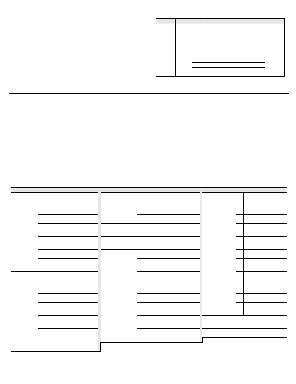
Set parameters b1-01 and b1-02 to their appropriate values. Refer to the table
to the right for available b1-01 and b1-02 values.
Refer to the appropriate programming or parameter access manual for a
complete list of drive parameters and registers available. A list of applicable
manuals is available at the end of this document.
Parameter Function
Data
Description
Default
0 Digital
Operator
1 Terminal
Strip
2
Built-in Modbus RTU
3
Option Card (Modbus TCP/IP Option
Kit)
b1-01
Frequency
Reference
Source
Selection
4
Pulse Input (F7 and G7 Only)
1
0 Digital
Operator
1 Terminal
Strip
2
Built-in Modbus RTU
b1-02
Run
Command
Source
Selection
3
Option Card (Modbus TCP/IP Option
Kit)
1
Important Modbus TCP/IP notes.
It is strongly recommended that shielded CAT-5 cable be used for all network cables.
A maximum of 10 simultaneous connections are allowed.
The run command and frequency reference may only be accessed through UNIT ID 1. While the drive is in remote run mode, the run command must be continually
refreshed within the configured EF0 timeout value. If the run command is not refreshed within the set timeout period, an EF0 fault will occur. Refer to the appropriate
drive manual for information on EF0 and setting the appropriate drive response. If a UNIT ID 1 connection is active, the NS/CON LED will blink at approximately a
500ms cycle.
The TCP/IP connection must be refreshed within 60 seconds. If it is not refreshed within 60 seconds, the connection will be closed.
This implementation of Modbus TCP/IP supports Modbus functions 3 (read multiple registers), 6 (write single register), 16 (write multiple registers), and 23
(read/write multiple registers).
Refer to the appropriate programming or parameter access manual (TM.XX.11) for a complete list of drive parameters and registers available. A list of applicable
manuals is available at the end of this document. Aside from command registers, Modbus TCP/IP and Modbus RTU share all other registers.
The table below lists the Modbus TCP/IP command registers. These are different from Modbus RTU command registers. These are designed to be used as part of the
standard PLC I/O or scan table, where fast response is required. Other register values should be accessed via individual messages, i.e. via an MSTR block.
Addresses 0001h, 0002h, 0003h, 0004h, 0007h, 0008h, and 0009h may be written while all other registers in the table below are read only. Addresses 0001h and 0002h
may only be accessed through UNIT ID 1 (see above).
Address
Description
Address
Description
Address
Description
0h Forward
Run
Input
Ah @ Remote Mode
4h EF7
External Fault 7
1h Reverse
Run
Input
Bh Multi-Function Output 1 (M1-M2)
5h
Reserved
2h Multi-Function Digital Input S3
Ch Multi-Function Output 2 (M3-M4)
6h
Reserved
3h Multi-Function Digital Input S4
Dh Multi-Function Output 3 (M5-M6)
7h
OS
Overspeed
4h Multi-Function Digital Input S5
Eh @ Motor 2 Selected
8h
DEV
Speed
Deviation
5h Multi-Function Digital Input S6
2000h
Status Word 1
(continued)
Fh @ Zero Servo Complete
9h
PGO
Encoder
(PG)
Loss
6h Multi-Function Digital Input S7
2001h
Speed Feedback Monitor (U1-05)
Ah
PF
Input
Phase
Loss
7h Multi-Function Digital Input S8 (G5/F7/G7)
2002h
Torque Reference Monitor (U1-09)
Bh
LF
Output
Phase
Loss
8h External Fault (EF0) Input
2003h
Encoder (PG) Count Channel 1 Monitor
Ch OH3 Motor Overheat 1
9h Fault
Reset
Input
2004h
Frequency Reference Monitor (U1-01)
Dh
OPR
Operator
Disconnected
Ah Multi-Function Digital Input S9 (G7)
2005h
Output Frequency Monitor (U1-02)
Eh ERR EEPROM Write Failure
Bh Multi-Function Digital Input S10 (G7)
2006h
Output Current Monitor(U1-03)
200Ah
Error Signal 2
(continued)
Fh OH4 Motor Overheat 2
Ch Multi-Function Digital Input S11 (G7)
2007h
Analog Input A2 Monitor (U1-16) (Terminal 14 for G5)
0h
CE
Communication
Loss
Dh Multi-Function Digital Input S12 (G7)
2008h
DC Bus Voltage Monitor (U1-07)
1h BUS Option Card Error
Eh Fault Log Trace Clear Input
0h PUF DC Bus Fuse Failure
2h
Reserved
0001h Command
Fh External Base Block Input
1h UV1 Main Circuit Undervoltage
3h
Reserved
0002h Frequency
Reference
2h UV2 Control Power Undervoltage
4h CF
Loss of Control
0003h Torque
Reference/Torque
Limit
3h UV3 Pre-Charge Contactor Failure
5h SVE Zero Servo Error
0004h Torque
Compensation
4h
Reserved
6h EF0
Option Card External Fault
0007h Analog Output FM (21 for G5)
5h
GF
Ground
Fault
7h FBL PID Feedback Loss
0008h Analog Output AM (23 for G5)
6h
OC
Overcurrent
8h
UL3
Undertorque
Detection
1
0h Multi-function Digital Output 1
7h
OV
Overvoltage
9h
UL4
Undertorque
Detection
2
1h Multi-function Digital Output 2
8h
OH
Drive
Overheat
Ah OL7 High Slip Brake Overload
2h Multi-function Digital Output 3 (G5/F7/G7)
9h OH1 Motor Overheat Alarm
Bh
Reserved
3h Multi-function Digital Output 4 (G5/F7/G7) Ah
OL1
Motor
Overload
Ch
Reserved
0009h
Multi-
function
Digital
Outputs
4h Multi-function Digital Output 5 (G5/F7/G7) Bh
OL2
Drive
Overload
Dh
Reserved
0h @
Run
Ch
OL3
Overtorque
Detection
1
Eh
Reserved
1h @ Zero Speed
Dh
OL4
Overtorque
Detection
2
200Bh Error Signal 3
Fh CPF Control Bd Hardware Fault
2h @ Reverse Direction
Eh RR
Braking Transistor Failure
200Ch Analog Input A1 Monitor (U1-15) (Terminal 13 for G5)
3h @ Fault Reset Active
2009h
Error Signal 1
Fh RH
Braking Resistor Overheat
200Dh Digital Input Status (Bit Field of Terminals S1-S8)
4h @ Speed Agree
0h EF3
External Fault 3
200Eh Analog Input A3 Monitor (U1-17) (Terminal 16 for G5)
5h @ Drive Ready
1h EF4
External Fault 4
200Fh PG Count Channel 2 Monitor (when PG-W2 is installed)
6h @ Minor Fault (Alarm)
2h EF5
External Fault 5
2010h Drive Software Number (U1-14)
7h @
Fault
200Ah
Error Signal 2
3h EF6
External Fault 6
8h @ OPE Fault (Keypad Setting Error)
2000h
Status
Word 1
9h @ Power Loss Ride Thru