Yaskawa GPD333 User Manual
Dynamic braking (db) option
DWG. NO. 02Y00025-0351
SHEET NO. 1 OF 7
EFF. 12/7/93
(m-df )
For GPD 333 230V 1/4-5HP,
460V 1/2-5HP
Adjustable Frequency Drives
CHANGE RECORD
1 STD-5980 2-16-95
DYNAMIC BRAKING (DB) OPTION
(BRAKING RESISTOR (3%) OR
BRAKING RESISTOR UNIT(10%))
(PART NUMBERS DETERMINED BY DRIVE RATING)
Before installing this option, a TECHNICALLY
QUALIFIED INDIVIDUAL who is familiar with this
type of equipment and the hazards involved, should
READ this ENTIRE INSTRUCTION SHEET.
IMPORTANT
This option may have been installed by the
factory. However, certain steps can only be
completed at the installation site. Therefore,
review and perform those steps which
complete the installation process.
DESCRIPTION
Installation of this option enables the motor to be
brought to a smooth and rapid stop. This is achieved
by dissipating the regenerative energy of the AC
motor across the resistive components of the
Dynamic Braking option.
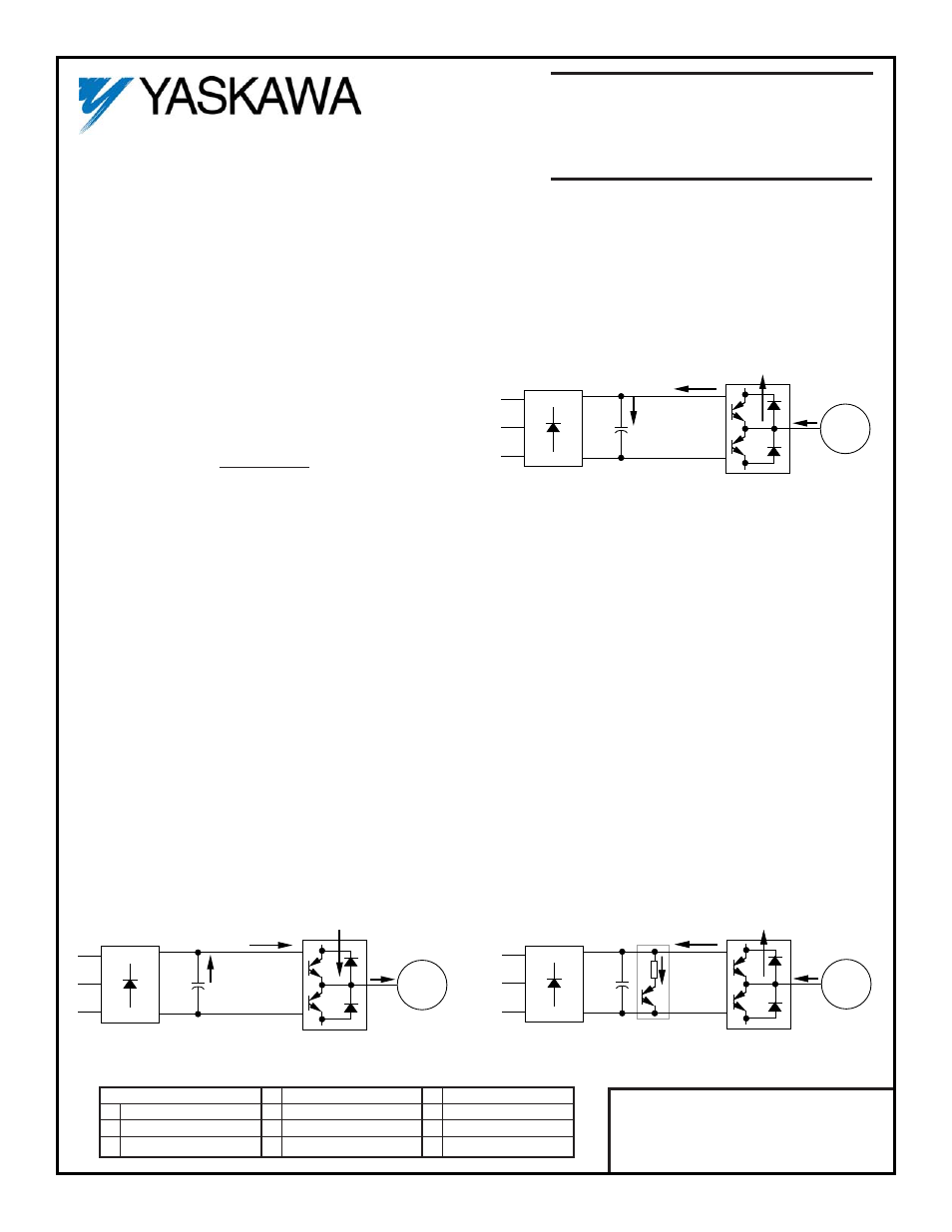
Dynamic Braking Operation
Whenever an excited motor is operated in the
negative slip region (or is subjected to an overhauling
load), the motor will behave as an induction
generator. In this mode, energy will actually flow from
the motor back into the drive, as shown in illustrations
(A) and (B).
This energy will cause the DC Bus voltage to rise.
Another condition that will cause the DC Bus voltage
to rise is when the input voltage to the drive is high.
When the DC Bus voltage reaches a certain level, the
Dynamic Braking option will activate. The option will
actually “shunt” the regenerative energy away from
the Bus capacitors, as shown in illustration (C), and
will dissipate it as heat in the DB resistors. Since the
regenerative energy is dissipated in the DC resistors,
the Overvoltage (OV) trip is prevented; thus the motor
remains excited and continues to produce braking
torque. However, for the high input voltage condition,
an input contactor (1M) should be used (see Figure 4
or Figure 5) to disconnect the drive when the high
input voltage exists for a long period of time.
BUS
CAPS
MOTOR
(A) "MOTORING" POWER FLOW
BUS
CAPS
MOTOR
(C) POWER SHUNTED FROM BUS CAPS
DB OPTION
BUS
CAPS
MOTOR
(B) "GENERATING" POWER FLOW