Yaskawa DI-16H2 User Manual
Page 2
5. Connect the grounding lead wire from the DI-16H2 card to terminal 12 on the Control Board.
6. Wiring. See Figure 3 and Tables 2 & 3 for Digital Reference Card (DI-16H2) connections. Connect digital
input signals to terminal blocks TC1 and TC2. Route wires from the GPD 515/G5 and connect to the peripheral
device(s). Refer to "Electrical Installation" in the GPD 515/G5 technical manual for further information on use of
shielded cable.
Table 1. Specifications of DI-16H2 Card
Parameter
Value
Input Data Signal
Binary 16 Bit/BCD 4 digits
Selected by swtich S1
Binary 12 bits/BCD 3 digits
SIGN and SET Signal Voltage
+24V
Control voltage input (from GPD 515/G5): 24V (isolated)
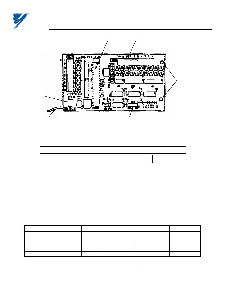
Figure 1. Digital Reference Card DI-16H2
Connector (on back side of card)
to Control Board (2CN)
2 mounting
holes
(0.16 in. dia.)
Terminal
block TC2
Terminal
block TC1
Switch S1
(for selecting input data configuration)
Terminal TC3
(for connecting
shielded
sheath)
Grounding lead wire (connects to
terminal 12 on Control Board)
Table 2. Applicable Wire Sizes For TC1 and TC2
Wire Type
mm
2
AWG
Current (Amps)
VAC
Thin twisted wire
1
16
12
125
Solid wire
1.5
16
12
125
UL
——
22-16
10
300
CSA
——
28-16
10
300
CSA
——
28-16
10
150
Yaskawa Electric America, Inc-www.drives.com
02Y00025-0400 Page 2 OF 5
REL. 05/21/96
DIGITAL REFERENCE CARD
(DI-16H2) MODEL DS016