Yaskawa Control Board Replacement Procedure for Large Capacity G7 Drives User Manual
Page 2
TM.G7.02
Page 2 of 5
Rev: 08-08, 08/22/2008
Control Board Replacement Procedure
for Large Capacity G7 Drives
Recommended Procedure for Replacing a Control Board in a CIMR-G7* 4055 to 4300
of Revision B or Later
Note: Follow all precautions in the drive’s technical manual, Document TM.G7.01, for safe wiring and operation of
the G7 Drive during auto-tuning.
Note: An appropriately sized motor with a FLA that closely matches the G7s rated output current needs to be
connected to the G7 while performing the Shipping Adjustment auto-tuning function. Tuning with a motor that is
considerably smaller than the G7 may adversely affect the performance of the G7.
Note: The motor will not rotate while performing Shipping Adjustment Auto-tuning. Therefore, the motor does not
need to be disconnected from the load. However, take appropriate precautions to secure the load and insulate the
motor terminals as voltage will be applied to the motor.
1. Before replacing the control board, use the COPY function of the digital operator to copy the G7 parameter
settings. When using the COPY function, first confirm the replacement control board software matches the
original control board software. The original control board software version can be viewed using the digital
operator by viewing monitor U1-14. Confirm the last 4 digits of the value monitored in U1-14 match the last 4
digits of the replacement control board part number (-SXXXX). The COPY function cannot be used if the
software version is different on the replacement control board. Manual parameter recording using the
Modified Constants Menu with the original control board will be necessary if the software versions do not
match. If in doubt, manually record the modified parameters as they appear in the original Control Board
Modified Constants Menu. In addition, record the setting of A1-02 (control method selection) for Step 4.
Item
Original Control Board
Value
Replacement
Control Board
Control Board Part Number
ETCXXXXXX-SYYYY
ETCXXXXXX-SYYYY
Software number (U1-14)
(confirm same as original
Control PCB)
Inverter capacity (o2-04)
(set same as original Control
PCB to match the drive’s
power rating. Refer to Step 3
below)
Control method (A1-02)
(set same as original Control
PCB. Refer to Step 4 below)
2. Replace the control board.
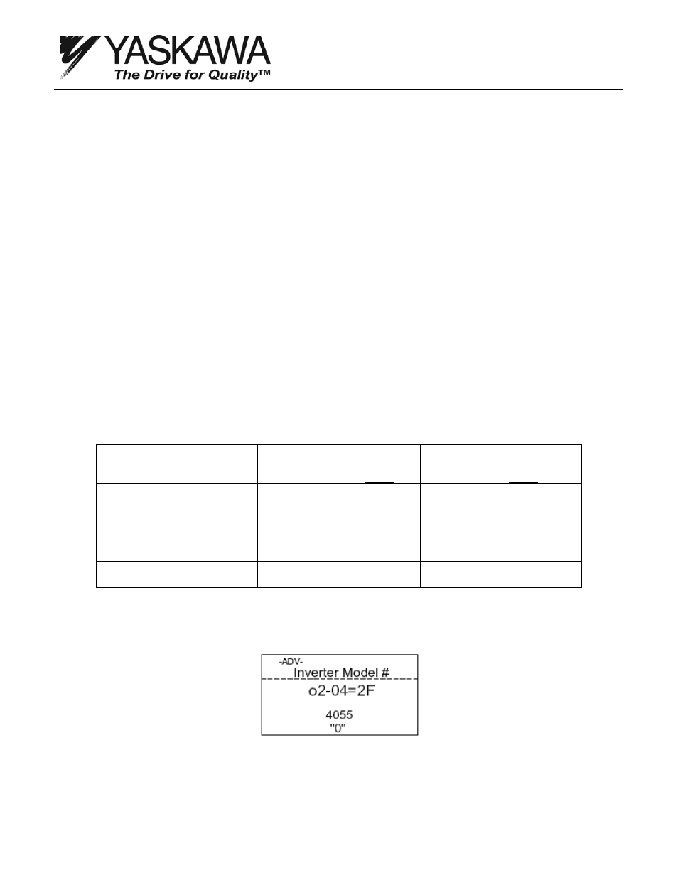
3. Change the kVA setting (o2-04) to match the G7s power section. See Figure 2.
Figure 2: Drive kVA Setting