Caution – Yaskawa DS391 User Manual
Page 3
DWG. NO. 02Y00025-0297
SHEET NO. 3 OF 7
REL. 01/30/91
( m - d f )
Refer to Sheet 1 for latest change.
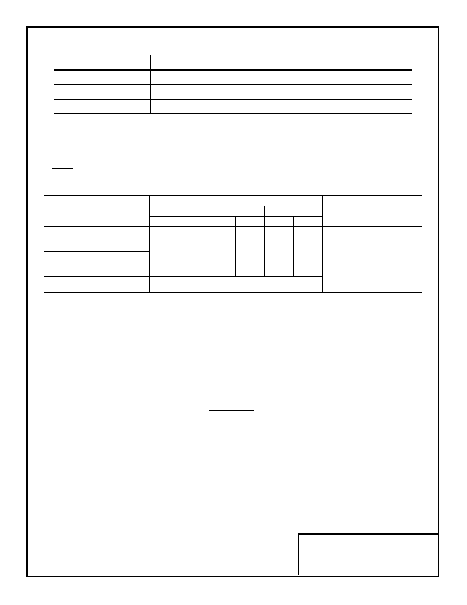
Table 1. Specifications
Parameter
Analog Monitor (AO-08)
Analog Monitor (AO-12)
Output Resolution
8 Bits (1/256)
11 Bits + sign (1/2048)
Output Voltage
0 to +10V (non-isolated)
–10V to +10V (non-isolated)
Output Channels
2
2
Control voltage input (from GPD 515, GPD 503 or VCD 703): 24V (isolated)
Table 2. Terminal Functions of AO-08 and AO-12
Signal Level
Terminal
Function
GPD 515
GPD 503
VCD 703
Notes
A0-08
A0-12
A0-08 A0-12
A0-08
A0-12
TD1
Analog signal
output channel 1
0 - 10V
0 - 10 V — Output impedance: 200
Ω
0 - 10V
or
0 - 10V 0 - 10 V 0 - 10V
or
TD2
Analog signal
±10V
±10V
— Terminal screws are metric
output channel 2
(1)
(2)
size M3.
TD3
Output Common
0V
(1)
Selectable by setting of drive parameter H4-07.
(2)
Selectable by setting of drive constant Sn-28 digit X X X X .
5. Connect the Analog Monitor's grounding (green) wire to terminal 12 of the drive.
6. Wiring. See Figure 3 for Analog Monitor connections. See Table 2 for terminal functions.
CAUTION
ANALOG MONITOR (I.E. CONTROL CIRCUIT) WIRING MUST
REMAINSEPARATE FROM MAIN CIRCUIT INPUT/OUTPUT
WIRING.
CAUTION
TO PREVENT ERRONEOUS OPERATION CAUSED BY NOISE
INTERFERENCE, USE SHEILDED CABLE FOR CONTROL
SIGNAL WIRING, AND LIMIT DISTANCE TO 50M (165 FEET) OR
LESS.