A1000 ac drive quick start procedure (olv), Page 2 of 2, Changing parameters and monitoring the a1000 – Yaskawa A1000 AC Drive Quick Start User Manual
Page 2: Selecting start/stop and speed method, Quick start parameters
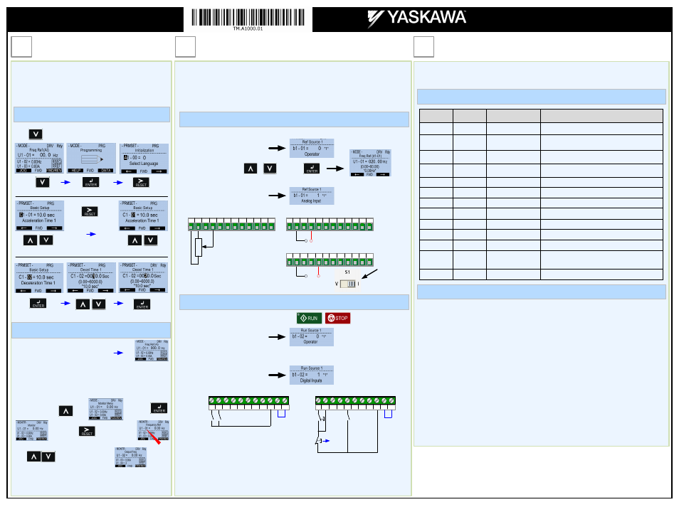
Step
5
Changing Parameters and
Monitoring the A1000
Step
6
Selecting Start/Stop and Speed Method
The following table lists the general purpose application parameters as well as frequently asked questions.
This section may require you to change one or more A1000 parameters. Please refer to Step 5 for a detailed
explanation on how to change parameters.
FREQUENTLY ASKED QUESTIONS
GENERAL PURPOSE APPLICATION PARAMETERS
Question: How do I reset the drive back to factory default settings?
Answer: Go to parameter A1-03 and set value 2
2220 for 2 wire control or 3
3330 for 3 wire control
(Please refer to Step 6 for wiring diagram)
Question: How do I adjust the time it takes the motor to speed up or slow down?
Answer: Adjust the acceleration time parameter C1-01 and deceleration time C1-02.
Question: How do I prevent my drive from tripping on an O
OV fault (overvoltage) while my motor is ramping down?
Answer: Increase deceleration time parameter C1-02.
Question: How do I prevent my drive from tripping on an O
OL1 fault (overload) while my motor is ramping down?
Answer: Verify motor rated current parameter E2-01 and motor overload parameter settings
L1-01 Motor overload selection, L1-02 Motor overload protection time.
Question: I want to run my motor above the nominal motor speed?
Answer: Increase the value of parameter E1-04 Maximum Frequency
W
Warning! Verify that the motor and system allow for this.
Yaskawa America, Inc.
2121 Norman Drive South
Waukegan, IL 60085
(800) YASKAWA (927-5292) Fax (847) 887-7310
[email protected] www.yaskawa.com
Document Number: TM.A1000.01 3/21/2013 © Yaskawa America, Inc.
Step
7
Quick Start Parameters
Parameter
Default Value
Description
Comments
b1-01
1
Reference Source
Speed Control Method
0 = Digital Operator (Adjust Motor Speed from keypad)
1 = Terminals (Speed Pot. / 0 – 10V / 4—20mA)
b1-02
1
Run Source /
Start/Stop Control Method
0 = Digital Operator (Start/Stop motor from keypad)
1 = Terminals (Start/Stop using external contact / switch)
b1-03
1
Stop Method Selection
0 = Ramp to stop (Motor ramps down at stop command)
1 = Coast to stop (Motor freewheels at stop command)
b1-04
0
Reverse Operation
0 = Allow motor to run in reverse direction
1 = Reverse direction prohibited
C1-01
10.0 sec.
Acceleration Time
The time it takes to ramp up from 0 to maximum motor speed.
C1-02
10.0 sec.
Deceleration Time
The time it takes to ramp down from maximum motor speed to 0.
C6-01
0
Heavy / Normal Duty
0 = Heavy Duty (Use for conveyor, mixer, applications)
1 = Normal Duty (Use for fan and pump applications)
d1-01
0.00 Hz
Frequency Reference
Frequency setting when speed is set from the keypad.
d2-01
100.0 %
Frequency Upper Limit
Maximum motor speed allowed (e.g. 100 % = Max rpm)
d2-02
0.0 %
Frequency Lower Limit
Minimum motor speed allowed (e.g. 100 % = Max rpm)
E2-01
*
Motor Rated Current
Motor nameplate current
L1-01
1
Motor Overload Selection
0 = Disabled
1 = Standard Fan Cooled Motor
2 = Standard Blower Cooled Motor
3 = Vector Duty Motor
L1-02
1.0 min
Motor Overload Time
Sets the motor thermal overload protection time.
Page 2 of 2
This step shows how to access and modify a A1000 parameter as
well as how to monitor A1000 signals such as output frequency
and motor current.
Make sure all protective covers have been re-attached and power
is turned on. D
DO NOT RUN THE MOTOR.
Press two times until the digital operator shows the parameter menu.
Select Digit
Access Parameter Menu and Change Parameter Value
Monitor Motor Frequency and Motor Current
To monitor output frequency and motor current or other signals
individually, press once, then press
. Next press to select monitor
Use to select monitor signal.
Please refer to the A1000 Technical Manual, (Document No.
SIEP C710616 41) on how to access other drive monitors.
U1-02 Output Frequency
2X
2X
Inc./Dec. Selection
Inc./Dec. Selection
Go to Next Digit
Switch to Edit Mode
Save New Value
Modify Value
A1000 Digital Operator power-up state
Output Frequency and Motor Current can be monitored
simultaneously.
Digits
Flashing
This step shows how to setup the sequence and reference method of the A1000. The sequence
method determines how the A1000 drive receives its start and stop command and the reference
method determines how the speed of the motor is controlled. Make sure all protective covers have
been re-attached and power is turned on. D
DO NOT RUN THE MOTOR.
This section may require you to change one or more A1000 parameters. Please refer to Step 5 for a
detailed explanation on how to change parameters.
SELECT START / STOP CONTROL METHOD
1.
Start / Stop Control from Digital Operator
Go to parameter b1-02, set value to
b1-02
2.
Start / Stop Control from external terminals (switch or relay contact)
Go to parameter b1-02, set value to
( Factory Default)
NOTE: It is beyond the scope of this document to program the A1000 drive for network communication control. Please refer
to the refer to the A1000 Technical Manual, (Document No. SIEP C710616 41) for this selection.
SELECT SPEED METHOD
b1-01
(Factory Default)
1.
Adjust motor speed / frequency from the Digital Operator
Go to parameter b1-01, set value to
2.
Adjust motor speed / frequency from external terminals (0 - 10V / 4 - 20mA Signal)
Go to parameter b1-01, set value to
(Factory Default)
+
Located inside
the drive on the
terminal board
To adjust frequency use / and press .
V+ AC V-
A1 A2 A3 FM AM AC MP
Potentiometer
2K Ohm
User Terminals
RP AC
V+ AC V-
A1 A2 A3 FM AM AC MP
User Terminals
RP AC
0 ~ 10Vdc
+
V+ AC V-
A1 A2 A3 FM AM AC MP RP AC
4 ~ 20mA
Note: 2
nd
row of terminal board is shown here.
S3
S5 S6 S7 S8 SN SC SP
S2
S4
S1
Wiring Diagram: 2-Wire Control
Forward
Reverse
Wiring Diagram: 3-Wire Control
Use for momentary contacts
Use for maintained contacts
User Terminals
User Terminals
(Set Parameter A1-03 to 3330)
Note: 3
rd
row of terminal board is shown here.
Link
S3
S5 S6 S7 S8 SN SC SP
S2
S4
S1
Start
Switch
Reverse
Stop
Switch
Normally
Open
Normally
Closed
Link
A1000 AC Drive
Quick Start Procedure (OLV)