Grass Valley Triton to Jupiter Serial Control Kit User Manual
Page 2
2
Note that the DC voltage switch is continuously variable and that the voltage level labels
are approximate.
4. Plug the BB–33 Universal Power Supply into AC power. Measure the DC voltage on
the output. Adjust the DC voltage switch until a 12 VDC reading is obtained.
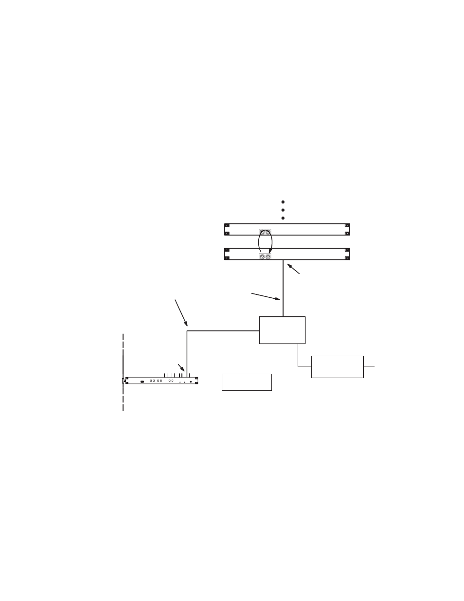
5. Connect the VM 3000 to Converter Cable, part number 01–050452–001, to an odd
number serial port on the VM 3000. See Figure 1.
Note 1: The even numbered ports on the VM 3000 will not work for this applica-
tion.
Note 2: The SI–3000 will not support Triton control.
Figure 1. Example of connection to Triton distribution switchers.
VM 3000 Control Processor
LAN
Converter to
Triton cable
Triton protocol
Serial port
Triton protocol avail-
able on odd–num-
bered ports only
B&B
RS–232/422
Converter
RS–232 port
MIDI bus loop
Triton Video
Triton L + R Audio
20 units maximum
Router address “0”
Router address “2”
VM 3000 to
Converter
Cable
B&B Universal
Power Supply
AC line
6. Connect the 25–pin end of the VM 3000 to Converter Cable to the RS–422 side of the
B&B converter. (Pinouts for this cable are shown in Figure 2.)
7. Connect the 9–pin end of the Converter to Triton Cable, part number
01–050453–001, to the RS–232 port on the Triton switcher.
8. Connect the 25–pin end of the Converter to Triton Cable to the RS–232 side of the
B&B converter.
9. With the power supply disconnected from AC power, connect the DC power connector
on the Universal Power Supply to the 12 VDC connector on the B&B Electronics RS
232 / RS 422 Converter.