2 overall view – Grass Valley ASD-771p User Manual
Page 10
ASD-771p/75/110 - Guide to Installation and Operation
3
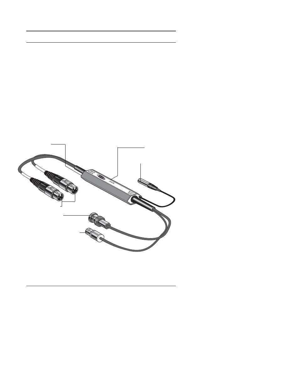
2 Overall view
The figures below represents the ASD-771p/75 and the ASD-
771p/110. The analog stereo audio source is connected to the
two XLR3 input connectors.
A multicolor LED provides module statuses. A mini slide switch
“Test” configures the test mode. The input level is configurable
using two 3-positions slide switches “Left” and “Right”.
Output is provided by a BNC socket over 75
Ω and a three-point
XLR connector over 110
Ω.
Power supply is connected to a mini-XLR type connector.
Figure 2.1 ASD-771p, 75
Ω Version
LEFT
RIGHT
Status LED
Input connectors
Slide switches
DC power input connector
Output connector
Reference input connector
See also other documents in the category Grass Valley Equipment:
- LDK 5302 (24 pages)
- SFP Optical Converters (18 pages)
- 2000GEN (22 pages)
- 2011RDA (28 pages)
- 2010RDA-16 (28 pages)
- 2000NET v3.2.2 (72 pages)
- 2000NET v3.1 (68 pages)
- 2020DAC D-To-A (30 pages)
- 2000NET v4.0.0 (92 pages)
- 2020ADC A-To-D (32 pages)
- 2030RDA (36 pages)
- 2031RDA-SM (38 pages)
- 2041EDA (20 pages)
- 2040RDA (24 pages)
- 2041RDA (24 pages)
- 2042EDA (26 pages)
- 2090MDC (30 pages)
- 2040RDA-FR (52 pages)
- LDK 4021 (22 pages)
- 3DX-3901 (38 pages)
- LDK 4420 (82 pages)
- LDK 5307 (40 pages)
- Maestro Master Control Installation v.1.5.1 (428 pages)
- Maestro Master Control Installation v.1.5.1 (455 pages)
- 7600REF Installation (16 pages)
- 7600REF (84 pages)
- 8900FSS (18 pages)
- 8900GEN-SM (50 pages)
- 8900NET v.4.3.0 (108 pages)
- Safety Summary (17 pages)
- 8900NET v.4.0.0 (94 pages)
- 8906 (34 pages)
- 8911 (16 pages)
- 8900NET v.3.2.2 (78 pages)
- 8914 (18 pages)
- 8912RDA-D (20 pages)
- 8916 (26 pages)
- 8910ADA-SR (58 pages)
- 8920ADC v.2.0 (28 pages)
- 8920ADC v.2.0.1A (40 pages)
- 8920DAC (28 pages)
- 8920DMX (30 pages)
- 8920ADT (36 pages)
- 8920MUX (50 pages)
- 8921ADT (58 pages)