3 operation – Grass Valley FLO-1601 User Manual
Page 8
GUIDE TO INSTALLATION AND OPERATION
4 | FLO-1601
3 Operation
3.1 Control
options
The FLO-1601 can be controlled in three different ways:
• The local control panel and its push-buttons can be used to move through a menu of parameters and to
adjust parameter values (see section 3.3).
• Miranda’s RCP-100 remote control panel can be used to access the same menu structure from a remote
location (see section 3.4).
• Miranda’s iControl system can be used to access the card’s operating parameters from a remote
computer, using a convenient graphical user interface (GUI). (not yet available)
3.2 Card-Edge Status LED
The status monitor LED is located on the front card-edge of the FLO-1601, and is visible through the front
access door of the DENSITÉ frame. This multi-color LED indicates the status of the FLO-1601 by color, and
by flashing/steady illumination.
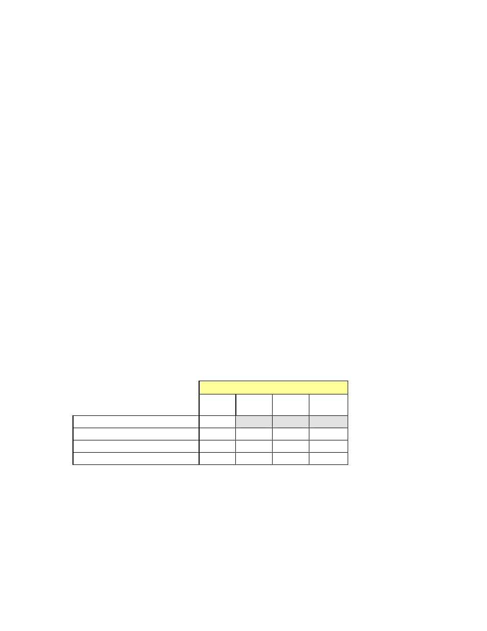
The chart shows how the various error conditions that can be flagged on the FLO-1601 affect the LED status.
• If a cell is gray, the error condition cannot cause the LED to assume that status
• If more than one LED status is possible for a particular error condition, the status is configurable.
(via the menu, and/or via iControl).
• The factory default status is shown by a
The LED will always show the most severe detected error status that it is configured to display, and in the
chart error severity increases from left to right, with green representing no error/disabled, and flashing red the
most severe error.
LED Status
Error Condition
Green Yellow Red
Flashing
Red
Status OK
No RF input
Weak RF input
Optical Out fail
: Factory default.
If the LED is Flashing Yellow, it means that the card is selected for local control using the Densité frame’s
control panel. See Section 3.3 for details.