Power up, Operation indicator leds – Grass Valley 8937 v.1.0.0 User Manual
Page 14
14
8937/8937D Instruction Manual
Power Up
Power Up
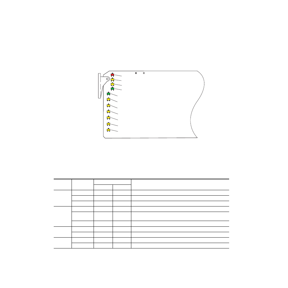
The front LED indicators and configuration switches are illustrated for the
8937 in
. The 8937D module has an addition row of identical LEDs
labeled for DA 1 and DA 2. Upon power-up, the green PWR LED should
light and the yellow CONF LED should illuminate for a few seconds for the
duration of module initialization.
Figure 7. LEDs and Configuration Switches
Operation Indicator LEDs
for the name and meaning of each of the board
edge operating indicators on the module circuit board.
Table 2. Board Edge LED Names and Meaning
LED
8937
8937D
Condition
DA 1
DA 2
FAULT
(red)
Off
Off
Off
Normal operation.
On continuously
On
On
Module has detected an internal fault. (Refer to
Long Flash
Long Flash
Long Flash
Input missing or input does not match bit rate set with manual mode.
COMM
(yellow)
Off
Off
Off
No activity on frame communication bus.
3 Quick Pulses
3 Quick
Pulses
3 Quick
Pulses
Locate Module command received by the module from a remote control system.
Short flash
Short flash
Short flash
Activity present on the frame communication bus.
CONF
(yellow)
Off
Off
Off
Module is in normal operating mode.
On continuously
On
On
Module is initializing, changing operating modes or programming hardware.
PWR
(green)
Off
Off
Off
No power to module or module’s DC/DC converter failed.
On
On
On
Normal operation, module is powered.
GRASS VALLEY 8937D SDI RECLOCKING EQ SNMP DA
8937
8270_05
FAULT (red)
COMM (yellow)
CONF (yellow)
PWR (green)
SIG PRES
143Mb
BYPASS
177Mb
270Mb
360Mb
REM OVR