Rear panel features, Inputs 1 and – EAW CAM160 User Manual
Page 5
CAM160 / CAM80 –
5
4. REAR PANEL FEATURES
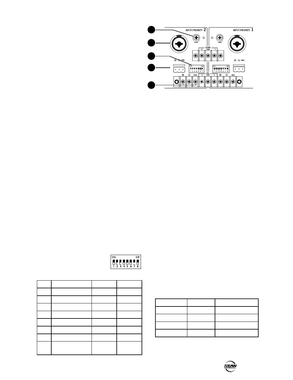
INPUTS 1 AND
Inputs 1 and 2 have identical connections and controls,
with the exception that Input 1 has an extra DIP switch to
select an internal transformer.
INPUT CONNECTORS
Inputs 1 and 2 each have four different styles of input
connections. Choose one which suits your system the best:
8. Combination XLR/TRS connector. This
can accept a male balanced XLR connector, a
balanced TRS or unbalanced TS 1/4" connector.
9. Phoenix (Euroblock) connector. This
three-pin connector accepts the positive, negative
and ground terminals of a balanced audio line. It
accepts a push-in connector for easy installation.
10. Terminal strip. This three-terminal connector
accepts the positive, negative and ground
terminals of a balanced audio line. Secure the
connections with the screws.
All inputs are designed to accept balanced or unbalanced
microphone-level signals, or may be configured to accept
line-level signals by means of the DIP-switch (see below).
11. GAIN pot and LED
This screwdriver-adjustable rotary potentiometer acts as a
trim control, and a red indicator LED displays the nominal
input level. With normal source material playing, adjust the
pot until the LED lights only occasionally during the loudest
moments of your program. (The LED will light 3 dB before
clipping.)
1. DIP switches
Input 1 has an eight-pole DIP-switch from which the inputs
(all four types) can be configured.
Input 2 has a seven pole DIP-switch,
identical to the first seven poles of
Input 1.
DIP switch details:
1. Mic/line (line-level is default). Select UP if using a
microphone, or DOWN if it is a line-level input such
as from a CD or DVD player. Note: You must set
DIP 2 to the same setting as DIP 1.
2. Mic/Line. Set this to whatever DIP 1 is set to. See
above for details.
3. Phantom Power. Select UP if using a microphone
that requires phantom power, otherwise, it is
important to keep this DOWN.
4. High-pass filter enable. The default position is
enabled (DOWN). This rolls off the low frequencies
below 120 Hz, at a rate of 12 dB per octave. Use
this to reduce low frequencies, such as from low
bass notes, microphone handling and stage noise.
It is useful when using smaller speakers that do
not reproduce the low frequencies well.
5. 10 dB pad enable. Select UP to reduce the input
level by 10 dB.
6. and 7. Ducking Threshold Select. Use these two in
combination to select the threshold when ducking
occurs. See Ducking Threshold and table below.
8. Transformer enable. Select UP to engage the in-
line audio transformer (input 1 only).
Ducking Threshold
DIP-switches 6 and 7 are used in combination with each
other to determine the threshold that the signals from input
1 or 2 must cross to initiate automatic ducking of the other
inputs. This table shows the combinations:
DIP # Purpose
DOWN
UP
1
Mic/Line
Line Level
Mic Level
2
Mic/Line
Line Level
Mic Level
3
24 V Phantom
OFF
Enabled
4
High Pass Filter
Enabled
OFF
5
-10 dB Pad Enable
OFF
Enabled
6
Ducking Threshold
OFF
see table
7
Ducking Threshold
OFF
see table
8
Transformer Enable
(input 1 only)
OFF
Enabled
DIP 6
DIP 7
RESULT
DOWN
DOWN
No Ducking
UP
DOWN
- 10 dB Duck threshold
DOWN
UP
- 20 dB Duck threshold
UP
UP
- 30 dB Duck threshold
1
9
10
8
11