How to connect di/do device to v23 / v24, How to connect di/do device, To v23 / v24 – ACTi V21 User Manual
Page 19: Encoder hardware manual
Encoder Hardware Manual
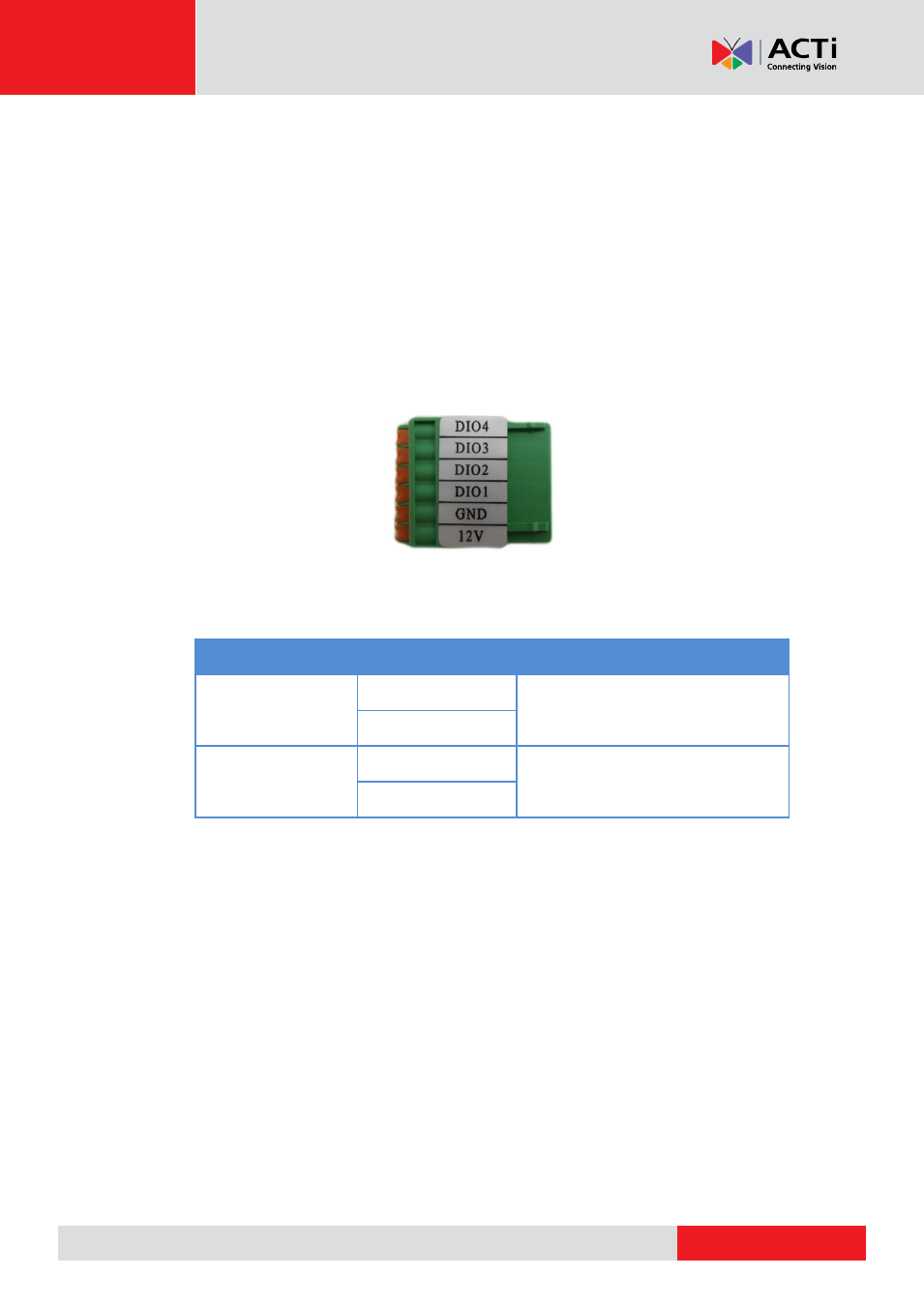
How to Connect DI/DO Device to V23 / V24
The digital input and output pins of V23 / V24 are configurable; meaning, either a digital input or
digital output device can be connected to a particular DIO pin. Once connected, the pin must be
defined through the Web Configurator (see the Encoder Firmware Manual for more information).
1.
Configure the DIO ports in Web Configurator (see the Encoder Firmware Manual for more
information).
2.
Press and hold the orange tab as you insert the wire through the pin slot, then release the
orange tab to secure the wire.
3.
To connect digital input / output devices (DI/DO), map the pins to one of the pin combinations
below:
Device
Pin Label
Mapping Instructions
Digital Output (DO)
DIO (port number)
Connect the wires of the output
device to a
DIO
and
12V
.
12V
Digital Input (DI)
DIO (port number)
Connect the wires of the input device
to
DI
and
GND
.
GND
NOTE:
For every digital output device, a wire must also be mapped to the
12V
pin. Same
with for every digital input device, a wire must also be mapped to the
GND
pin. The
GND
and
12V
pins may be mapped with more than one device.
4.
Connect the terminal block to the DIO connector of the encoder.