Hardware manual – ACTi D21FA User Manual
Page 17
Hardware Manual
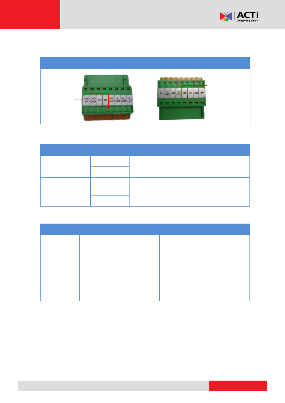
Press and hold the orange tab as you insert the wire through the pin slot, then release the orange
tab to secure the wire. The terminal block label varies depending on camera model.
D2xxA / E2xxA / E2xA / E27x
E23B
To connect digital input / output devices (DI/DO), map the pins to one of the pin combinations
below:
Device
Pin
Mapping Instructions
Digital Output (DO)
DIO PW / 12V
Connect the wires of the output device to
DIO
PW
or
12V
and
DO
.
DO
Digital Input (DI)
DIO GND or
GND
Connect the wires of the input device to
DIO GND
or
GND
and
DI
.
DI
The table below shows the DI/DO connection specifications:
Device
DI
Connection design
TTL - compatible logic levels
Voltage
To trigger (low)
Logic level 0: 0V ~ 0.4V
Normal (high)
Logic level 1: 3.1V ~ 30V
Current
10mA ~ 100mA
DO
Connection design
Transistor (Open Collector)
Voltage & Current
< 24V DC, < 50mA
For DI/DO Use
For DI/DO Use