3 front panel led’s and push buttons – Westermo U200 Installation guide User Manual
Page 13
V4.2
www.westermo.com
U/R/T200 series
- 13 -
•
Link / Port 1 to Port 8 Failure
The user can connect to the fault contact, STAT pin on power connector, see Figure 6, with a
pull-up resistor to Vin.
The fault contact implementation is described in details in the Operator Manual.
3.3 Front panel LED’s and Push Buttons
3.3.1 Manual Configuration
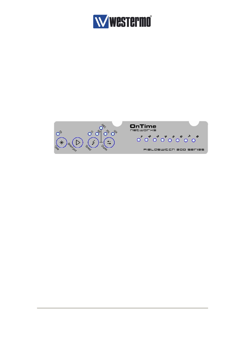
The front panel LEDs provides indication on the Status of each port. In addition, each port can
be manually configured for speed, duplex and auto-negotiation can also be set from the push
button panel. The LED/push button panel is shown in the figure below.
Figure 7, LED’s and push buttons
3.3.2 Normal Indication Mode
When the unit is first powered on the Switch front panel LEDs will run in normal mode. In this
condition the port LED will indicate link and traffic status.
3.3.3 Select Port Mode
The front panel will enter Select Port Mode when the Select Port button is pressed. Pressing
the Select Port button once will illuminate Port 1 LED – manual control of this port is now
available. Pressing the Select Port button a second time will illuminate Port 2 LED – manual
control of this port is now available. Each additional port can be placed into Manual mode by
subsequent pressing of the Select Port button.
If no buttons are pressed for 30 seconds the unit will return back to Normal Indication Mode.
3.3.4 Speed Button
Pressing the Speed button once selects 10M, twice enables 100M.
3.3.5 Duplex Button
Pressing the Duplex button changes the Port duplex mode from full duplex to half duplex and
vice-versa.