Connections tr-36 – Westermo TR-36 User Manual
Page 11
11
6614-2202
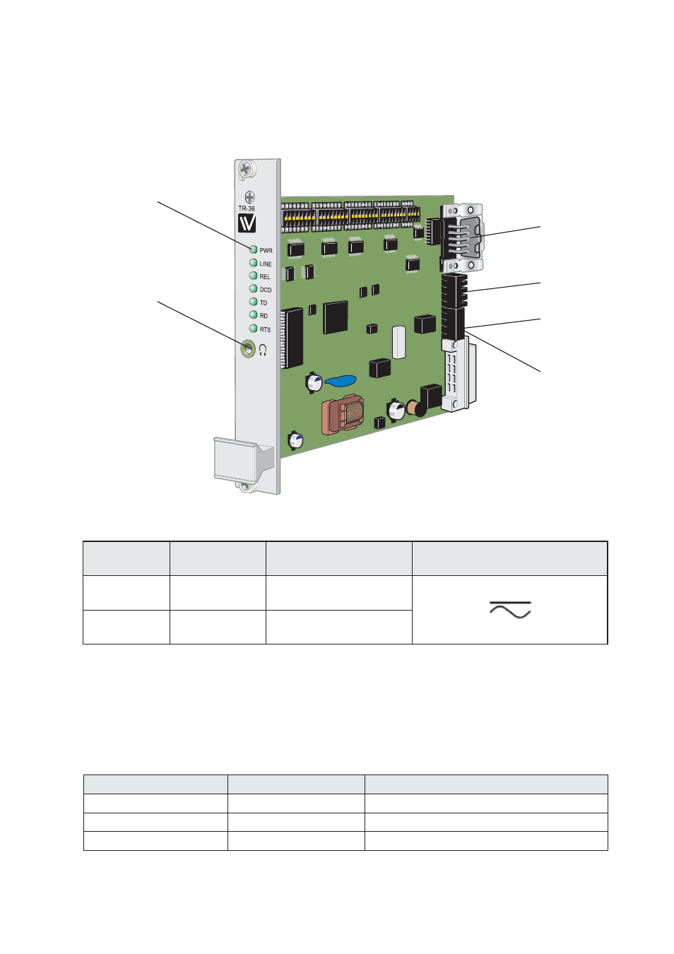
4
3
2
1
4
3
2
1
Leased Line
PSTN
RS-422/485
RS-232
LED Status Indicators
Connections
TR-36
Jack socket
Power
Position
Direction*
Description
Product
marking
1
In
AC: Neutral
DC: – Voltage
2
In
AC: Line
DC: + Voltage
To minimise the risk of interference, a shielded cable is recommended when the cable is located inside 3 m
boundary to the rails and connected to this port.
The cable shield should be properly connected (360°) to an earthing point within 1 m from this port. This earth-
ing point should have a low impedance connection to the conductive enclosure of the apparatus cabinet, or
similar, where the unit is built-in. This conductive enclosure should be connected to the earthing system of an
installation and may be directly connected to the protective earth.
PSTN
Position
Direction*
Description
Screw terminal*
2
In/Out
PSTN Transmit/ Receive
1
In/Out
PSTN Transmit/ Receive
* The PSTN screw terminals are shared with 2-wire Leased line
- TR-36B (88 pages)
- TD-36 (44 pages)
- TR-36B (20 pages)
- IDW-90 AT (97 pages)
- GD-01 (20 pages)
- GD-01 (206 pages)
- MRI-128-F4G (175 pages)
- MRI-128-F4G (169 pages)
- GDW-11 485 (380 pages)
- GDW-11 (40 pages)
- Lynx Series (28 pages)
- ODW-720-F2 (36 pages)
- ODW-720-F1 (20 pages)
- ODW-720-F1 (24 pages)
- ODW-730-F2 (36 pages)
- ODW-730-F1 (24 pages)
- DDW-120 (24 pages)
- DDW-226-EX (24 pages)
- DDW-226-EX (24 pages)
- DR-270 (28 pages)
- DR Series (460 pages)
- ED-2x0 (20 pages)
- MRD-3x0 (199 pages)
- FD-80 (24 pages)
- FDV-206-1D-1S (24 pages)
- GD-01 US (24 pages)
- LD-01 (8 pages)
- IDW-90 (44 pages)
- Lynx-x10-F2G (16 pages)
- Lynx-x08-F2G-S2 (20 pages)
- MDI-110-F3x (16 pages)
- MR-2x0 (28 pages)
- ODW-642 (28 pages)
- PII PoE Injector (12 pages)
- Viper Series (977 pages)
- SDI-5xx (12 pages)
- RFI-xx (32 pages)
- SDI-8xx (16 pages)
- RFIR-xxx (24 pages)
- TD-29 (16 pages)
- SDW-5xx (24 pages)
- TD-23 (24 pages)
- TD-29P (16 pages)
- Viper 408 (20 pages)