Introduction, Mounting the unit, Wiring the power inputs – Westermo MCI-211G User Manual
Page 2: Package contents check list
The MCI-211G Industrial Gigabit Ethernet Converter, conforming IEEE 802.3 10Base-T, 802.3u
100Base-TX and 1000Base-T/SX/LX standard, supports RJ-45 copper to Gigabit fiber conversion using
store and forward technology. The MCI-211G adopts rugged metal case design to operate in harsh
environments (-25~70
o
C); It also provides IP-31 standard protection. It features Link Fault Forwarding
to raise an alarm when a remote fault occurs and also adopts one relay output to alarm users if a port
link fails or if the power fails. Alarms can be enabled/ disabled by dip switch. The fiber port supports
SFP socket for several of SFP transceiver to achieve different link distance.
MCI-211G is recommended to be powered by DC 24V with 12~48V range from the 6-pin removable
terminal block.
Introduction
Box contents
MCI-211G
Quick Installation Guide
Mounting the Unit
Din-Rail mount: Mount the din-rail clip screwed
on the rear of MCI-211G on the DIN rail.
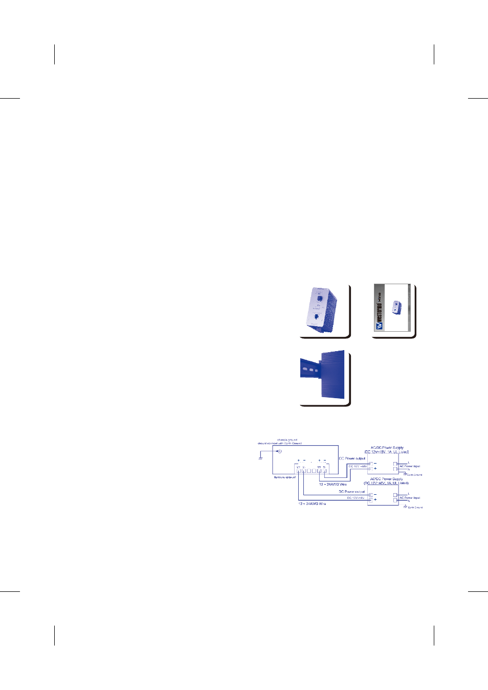
Wiring the Power Inputs
1. Insert the positive and negative wires into the
V+ and V- contact on the terminal block connector.
2. Tighten the wire-clamp screws to prevent the
DC wires from being loosened. See Figure-1
Notes: The recommended working voltage
is DC24V (DC12~ 48V)
Package contents Check List
Figure-1
MCI-211G
MCI-211G
DC1
DC2
Alarm
A
B
L
ZhiZgbd
IZaZ^cYjhig^
67
lll#lZhiZgbd#Xdb
>cYjhig^Va<^\VW^i:i]ZgcZi
H;EBZY^V8dckZgiZg
MCI-211G
Fj^X`>chiVaaVi^dc