Connections ld-63, Power connection ld-63 lv, Power connection ld-63 hv – Westermo LD-63 HV User Manual
Page 12
12
6072-2005
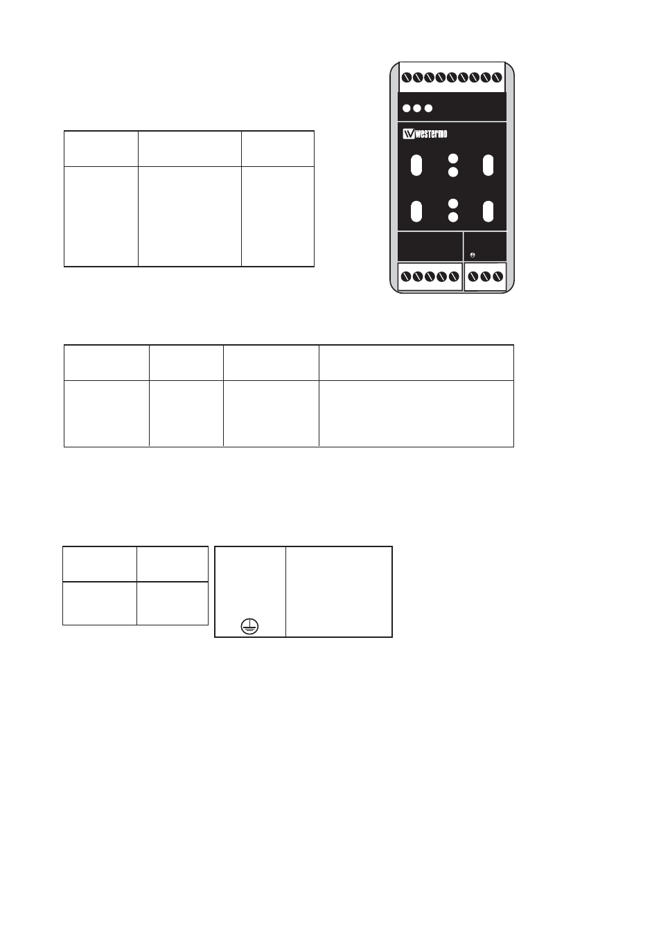
Connections LD-63
Line connection
(5-position screw-terminal)
Terminal connection (DCE)
(RS-232-C/V.24, 9-position screw-terminal)
Direction Connection
ITU-T
V.11
no.
Description
Receiver 1
A’
(R+)
Receiver 2
B’
(R–)
Transmitter 3
A
(T+)
Transmitter 4
B
(T–)
5
Shield
Direction
Screw
ITU-T
V.24
Description
no.
Description
I 8 103
TD/Transmitted
Data
O 7 104
RD/Received
Data
– 9 102
SG/Signal
Ground
I = Input O = Output on LD-63
LEDs for indication on LD-63
• PWR: Indicates that the converter has power.
• TD: Indicates that the converter is receiving data on RS-232/V.24, RS-485 side.
• RD: Indicates that the converter is sending data on RS-232/V.24, RS-485 side.
• Rx1: Indicates received data on fiber channel 1.
• Rx2: Indicates received data on fiber channel 2.
• Tx1: Indicates that the converter is sending data on fiber channel 1 from RS-232/V.24, RS-485 side.
• Tx2: Indicates that the converter is sending data on fiber channel 2 from RS-232/V.24, RS-485 side.
The definations R+/R–, T+/T– can be various between
different manufactures.
Power connection
LD-63 LV
(2-position screw-terminal)
Connection Power
no.
supply
1
–
Voltage
2
+
Voltage
Connection
Power
no.
supply
L
+
Voltage
N
–
Voltage
PE/
Protective
Earth
Power connection
LD-63 HV
(3-position screw-terminal)
1
2
3
4
5
L
N
LD-63
RS-422/485
POWER
R+
Rx1
Rx2
Tx1
Tx2
R- T+
T-
TD RD
PWR