La-01 dc – Westermo LA-01 User Manual
Page 4
8
6110-2012
Direction
Pin configuration 10 mA balanced current loop
W1
Channel 1
Channel 2
Channel 3
Description
Receiver
1
1
1
(R+)
Receiver
2
2
2
(R–)
Transmitter
3
3
3
(T+)
Transmitter
4
4
4
(T–)
5
5
5
Shield *
* If shielded cable is used, connect the shield only at one end to avoid ground currents.
10 mA balanced current loop
Transmission range (10 mA balanced current loop)
Cable
Transmission speed bit/s
42 pF/m
600
1 200
2 400
4 800
9 600
19 200
38 400
0.3 mm
2
18 000 m
12 000 m
8 000 m
5 000 m
2 500 m
1 000 m
500 m
LA-01 DC
Specifications
Switch settings
According to LA-01 AC
Power supply
12–36 V DC
Power consumption
Max 3 W
Isolation
1000 V
Fuse F1
1.6 A fast 5x20 mm
All other specifications according to LA-01 AC
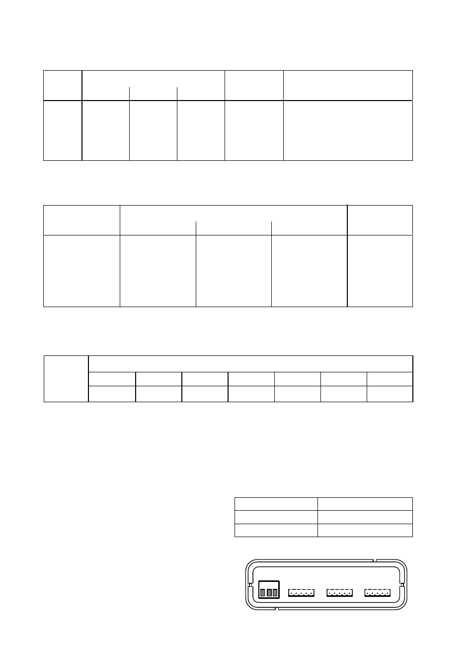
Connections
According to LA-01AC, except power supply
Connection no.
Power supply
1
+ Voltage
2
– Voltage
1 2 3
POWER
12-36VDC
CHANNEL 3
CHANNEL 2
CHANNEL 1
Direction
RS232-C/V.24
ITU-T V.24
Description
Circuit no.
I
1
1
1
103
TD/Transmitted Data
O
2
2
2
104
RD/Received Data
O
4
4
4
–
+12 V (Pull-up resistor)
–
5
5
5
102
SG/Signal Ground
I = Input, O = Output on LA-01
Connections
RS-232-C/V.24
Channel 1
Channel 2
Channel 3