Start up guide – Westermo ODW-710-F1 User Manual
Page 17
17
6651-2201
Start up guide
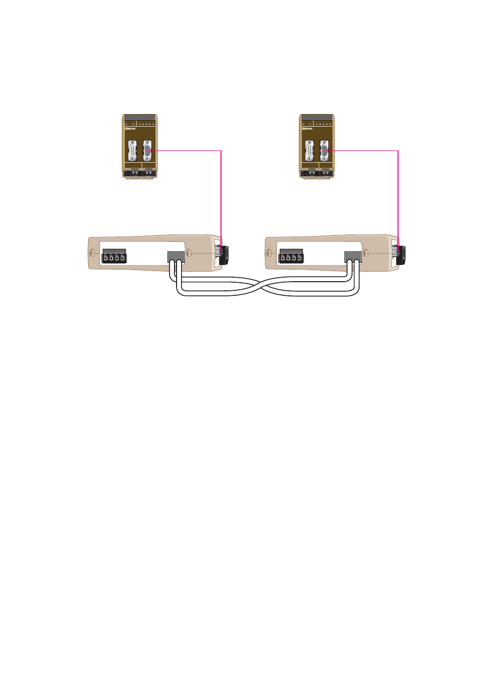
Follow the steps below to get the unit up and running in a simple application.
… Use the factory DIP-switch settings.
… Connect The fibre link between the both units.
… Connect the power supply to both units.
The Fibre link should be in operation as indicated by the CH1 LED.
… Connect the PROFIBUS DP connectors between both ODW-710-F1 and PROFIBUS
units configured to be units in the PROFIBUS DP network.
The PROFIBUS DP will be in operation and the data rate will be automatically detect-
ed, as indicated by the BA LED.
… The point to point application is up and running.
Note: In an ODW-710-F1 fibre optic link there will be some additional processing
delays that do not exist in an electrical bus. It is possible that the PROFIBUS
application must be adjusted to accommodate for this delay. See page 21
“Calculating system processing delay” for more information on how to
determine the overall system delay time.
POWER
CH 1
COM +VA +VB COM
POWER
CH 1
COM +VA +VB COM
TX
RX
TX
RX
PROFIBUS DP master
Fibre Optic
PROFIBUS DP
PROFIBUS DP
PROFIBUS DP slave