Hints – Westermo LD-01 User Manual
Page 6
12
6154-2001
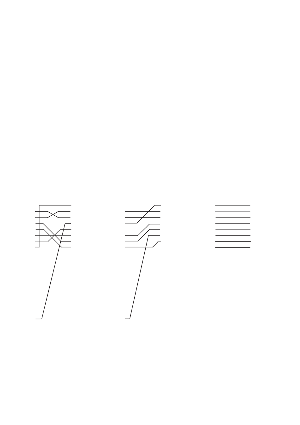
1
2
3
4
5
6
7
8
9
LD-01
1
2
3
4
5
6
7
8
9
9-pos. PC
1
2
3
4
5
6
7
8
9
10
11
12
13
14
15
16
17
18
19
20
21
22
23
24
25
1
2
3
4
5
6
7
8
9
DTE
LD-01
1
2
3
4
5
6
7
8
9
10
11
12
13
14
15
16
17
18
19
20
21
22
23
24
25
1
2
3
4
5
6
7
8
9
DCE
LD-01
Hints
LD-01 has four channels. Channel 1 has RS-232 interface and channel 2 and 3 can be
configured as RS-232 or W1 interface. Channel 4 has only W1 interface. The LD-01
splits the line and repeats the signal in a multidrop system. The maximum number of
units in serial connection is 14 units.
The drop channel (no 1) is configured as DCE (Data Communication Equipment). Most
printers, PC’s and terminals are set as DTE (Data Terminal Equipment). A recommen-
dation of cable configurations is given below.
If any problems do occur on set up of the LD-01:s, the LED’s may be helpful.
• PWR:
The unit has power.
• RD channel 1:
Indicates transmitted data from channel 1
• TD channel 1:
Indicates received data on channel 1
• DCD channel 2:
Indicates that W1 is connected to channel 2
• DCD channel 3:
Indicates that W1 is connected to channel 3
• DCD channel 4:
Indicates that W1 is connected to channel 4