Redundant ring, dual channel, y-mode configuration, Prepare the fibre optical network – Westermo ODW-730-F2 User Manual
Page 21
21
6651-2255
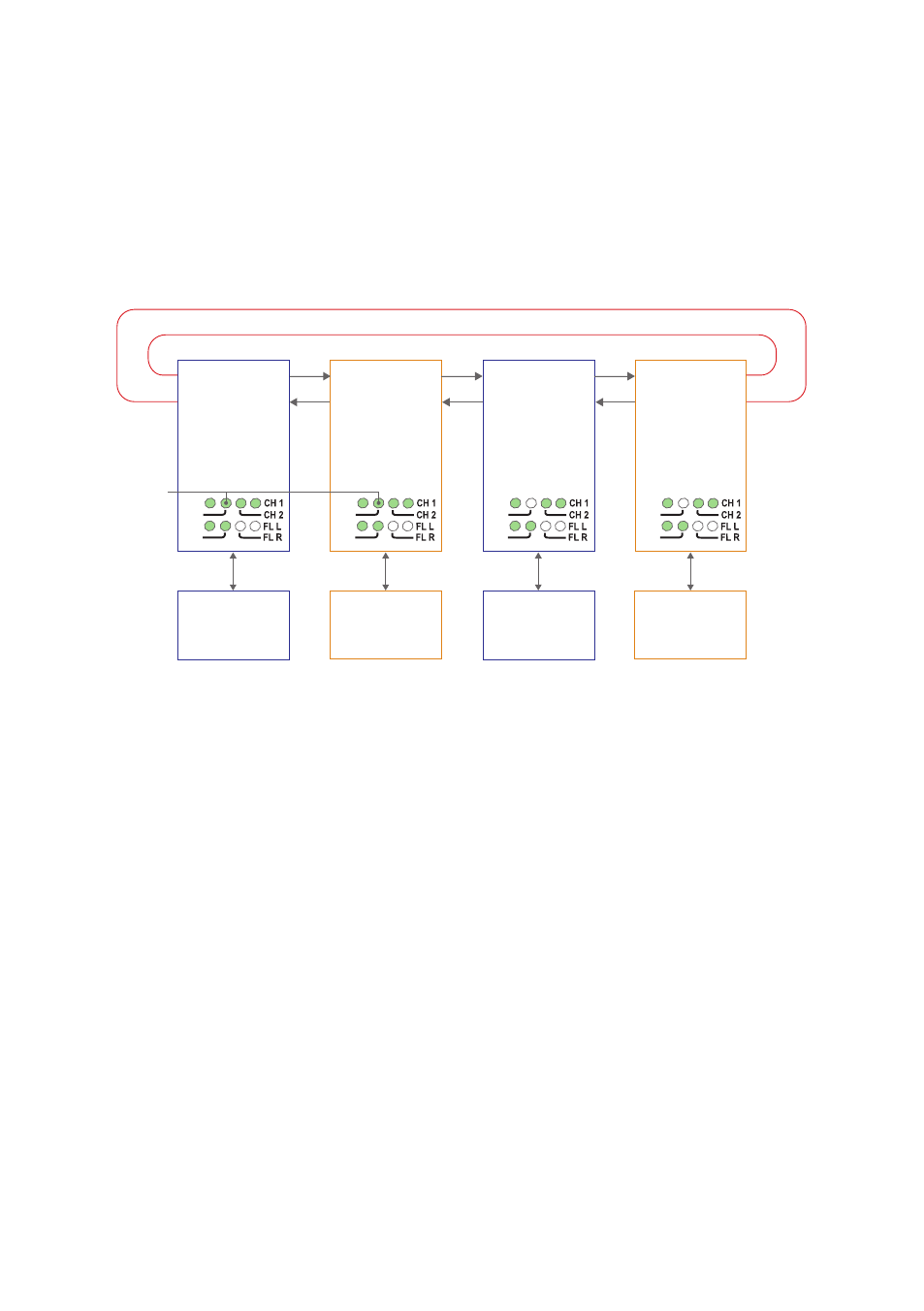
Redundant ring, dual channel, Y-mode configuration
In a redundant ring an extra fibre pair is used. This extra fibre pair is used to carry data if
one of the other fibre pairs breaks.
In dual channel mode it is possible to use two separate data streams in a single ODW-
730 network. However, all ODW-730’s must be set to the same speed and data format.
This, of course, limits the number of possible applications for a dual channel network.
In Y-mode mode an ODW-730 network will behave as a 2-wire bus. I.e. all communica-
tion devices will “hear” the data sent out by other communication devices.
RX2
TX2
Primary channel
Focal point
S2: 2 ON
S2: 3 ON
S2: 4 OFF
S2: 5 ON
Device 1
Communicates
with device 3 on the
primary data channel
TX1
RX1
RS-485
PWR
FP
TD
RD
RX2
TX2
Secondary channel
Focal point
S2: 2 ON
S2: 3 ON
S2: 4 ON
S2: 5 ON
Device 2
Communicates
with device 4 on the
secondary data channel
TX1
RX1
RS-485
PWR
FP
TD
RD
RX2
TX2
Primary channel
Ring member
S2: 2 ON
S2: 3 OFF
S2: 4 OFF
S2: 5 ON
Device 3
Communicates
with device 1 on the
primary data channel
TX1
RX1
RS-485
PWR
FP
TD
RD
RX2
TX2
Secondary channel
Ring member
S2: 2 ON
S2: 3 OFF
S2: 4 ON
S2: 5 ON
Device 4
Communicates
with device 2 on the
secondary data channel
TX1
RX1
RS-485
PWR
FP
TD
RD
Redundant fibre pair. Not used under normal operation.
Fibre
pair
Fibre
pair
Fibre
pair
FP LED
is on to
indicate
focal point
Prepare the fibre optical network
• Configure all ODW-730 units for the correct speed and data format using DIP-
switches S1:1 – S1:7. Again, notice that all ODW-730’s must be set to the same speed
and data format.
• Select RS-485 2 wire and 4-wire mode using DIP-switch S2:1 (OFF = 2-wire,
ON = 4-wire).
• Enable the RS-485 termination / fail-safe if required using DIP-switches S3:1 – S3:4
(S3:1 and S3:2 = 4-wire termination, S3:3 and S3:4 = 2-wire termination)
• Set DIP-switch S2:2 in the ON position (redundant ring) on all ODW-730 units.
• Set DIP-switch S2:5 in the ON position (dual channel system) on all ODW-730 units.
• All ODW-730 units that are to use the primary data channel (“blue” units in the
picture above) must have DIP-switch S2:4 set to the OFF position. Units that are to
use the secondary data channel (“orange” units in the picture above) must have DIP-
switch S2:4 set to the ON position.
• One of the primary data channel and one of the secondary data channel ODW-730
units must be configured as a Ring Focal Point by setting DIP-switch S2:3 to the ON
position.
• Set DIP-switch S2:6 as desired. See page 34 “Status port” for more information.
• Verify that DIP-switches S1:8, S2:1 and S2:8 are set in the OFF position.