Watson-Marlow 505U User Manual
Page 4
4
•
Change the set speed by pressing the ¿ or À key. The 505U speed control ratio is 110:1. This will give a minimum speed of
2rpm for the 220rpm drive and 0.5 rpm for the 55rpm drive.
•
Change direction by pressing the CW/CCW key. Check the flashing CW/CCW symbol for actual direction setting. (CW:
clockwise CCW: counterclockwise).
•
Select the maximum speed: press the ¿ key and the Max key together. Select the minimum speed: press the À key and the
Max key together.
•
The keypad has a locking facility to avoid resetting or tampering. If the pump is stopped, press Stop until the padlock symbol
illuminates. If the pump is running, press Start until the padlock symbol illuminates. All keys will be disabled except for Start and
Stop. Press these keys until the padlock symbol extinguishes to unlock the keypad.
•
The pump can be set to automatically restart in its operating state set prior to interruption, or set so that after power is
reconnected the pump will remain stopped. To invoke the Auto-restart facility switch off power to the pump at the mains supply.
Press the Start key down when the mains supply is switched back on until the ! symbol illuminates. Now press Start to start
the pump. This facility can be cancelled by turning the mains supply off and then pressing the Stop key whilst turning the mains
supply back on. The ! symbol will not be illuminated.
•
Press Start to start the pump. Press Stop to stop the pump.
Automatic operation
Press the Man/Auto key. When the AUT symbol flashes the pump is in manual mode.
The pump is controllable by an analogue process signal of up to 30V or 32mA. The pump will provide an increasing flow rate for
rising control signal (non-inverted response ) or an increasing flow rate for falling control signal (inverted response).
•
Signal offset is the process signal level which has to be reached in order for the pump rotor to start rotating.
•
Signal range is the change in process signal level necessary to produce the required change in pump rotor speed.
For example, when using a 4mA to 20mA process signal:
Pump response
Signal offset
Signal range
Non-Inverted 4mA
16mA
Inverted 20mA
16mA
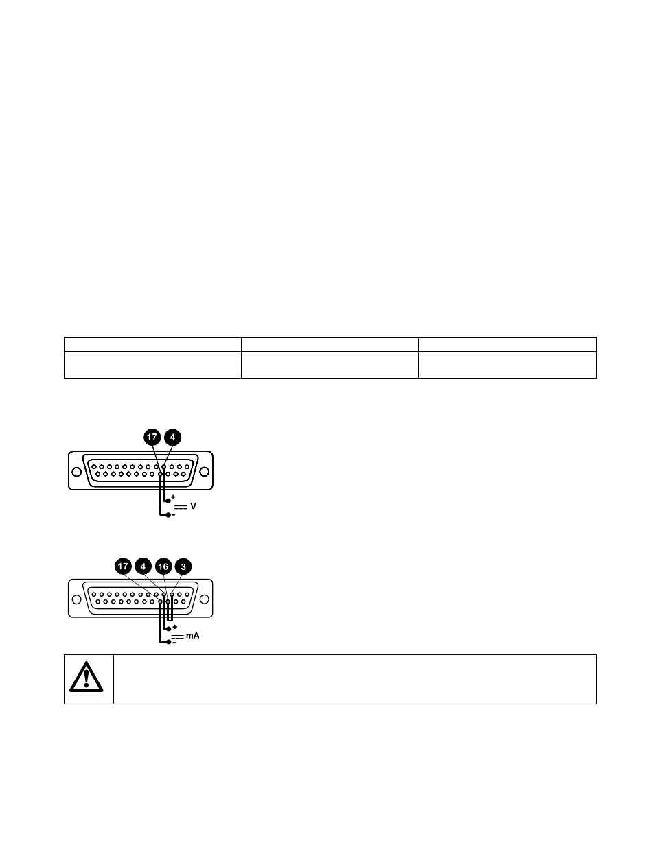
For voltage modes a stable variable DC voltage source can be used in conjunction with a DC voltmeter, (maximum 30V DC). (Refer
to 25D pin connector wiring detail as an example of control circuitry) Circuit impedance 100 kohms. Polarity set for non-inverted
response. Reverse polarity for inverted response.
For current modes the same DC source can be used in conjunction with a DC milliampere meter, (maximum 32mA). (See 25 pin
Dee connector detail). Circuit impedance 250 ohms. Polarity set for non-inverted response. Reverse polarity for inverted response.
Never apply mains voltage across any pins on the 25D socket. Up to 30V may be applied across pins 4 and
17, and 5V TTL on pins 7 and 5, but no voltage should be applied across other pins. Permanent damage, not
covered by warranty may result in both instances. Do not use the mains power switch to control the pump
for a high repetition of stop/starts. The auto-control facility should be used.
Calibration procedure
•
Turn the signal offset potentiometer (marked "Offset" on back panel) clockwise until the slider traverse limit is reached and is
signified by a clicking noise. Now turn the potentiometer ten turns anticlockwise. Repeat for the signal range potentiometer. This
ensures correct potentiometer set up for calibration.
•
Set the process signal offset.