Wet end assembly – Watson-Marlow MasoSine Ecosine Assembly User Manual
Page 2
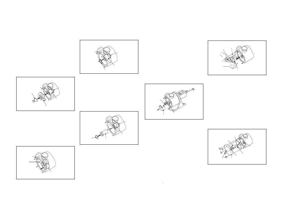
6. Place the scrapergate, item 125, into the scrapergate guide,
item 100, being sure that the marked ends (SL and SR) match
up properly. See Appendix 2 in the instruction manual for
detailed description of scrapergate/scrapergate guide
orientation. With the scrapergate and guide in the desired
orientation, place the assembly onto the rotor, item 011, fitting
the “slot” over the rotor vane. With two hands, insert the three
piece assembly into the pump by placing the scrapergate guide
into the bore between the nozzles and fitting the rotor over the
splined section of the shaft. Once the rotor meets the o-ring
on the shaft sleeve, apply extra pressure to seat the o-ring
properly.
1. Lubricate the seal housing o-ring, item 540, with a food grade
grease and insert it into the groove at the rear of the pump
housing.
2. If the seal housing, item 500, is stainless steel, place the
dynamic face o-ring, item 515, into the groove on the the seal
housing face. Again apply a food grade lubricant to the o-ring.
Then place the seal housing over the shaft and into the rear
bore of the pump housing with the removal holes exposed. If
the seal housing is stainless steel, the anti-rotation pin
located at the rear must be properly located into the slot in
the rear of the pump housing.
5. Install one of the liners, item 072, into the pump housing and
locate it between the anti-rotation pins on the I.D. of the pump
housing as shown. Apply even pressure at both ends to
prevent the liner from lodging in the pump housing.
3. To properly seat the seal housing, place the rotor, item 011, and
shaft nut, item 231, onto the shaft and tighten the nut until the
seal housing is forced past the seal housing o-ring. Remove
the rotor and shaft nut from the shaft before proceeding.
9. Apply a food grade lubricant to the front cover o-ring, item
430, and place it into the groove on the pump housing face.
10. If the scrapergate support, item 370, is stainless steel,
lubricate the dynamic face o-ring, item 515, and place it into
the groove on the end of the support. Next, place the
scrapergate support into the center bore of the front cover,
item 400, slotted end first. If the support is stainless steel,
be sure the anti-rotation pins fit into the relief slots in the
cover.
11. Place the front cover and scrapergate support assembly onto
the pump housing by aligning the studs, item 450, with the
corresponding holes in the cover. Front cover pins, item 420,
have been provided to facilitate this.
12. Install the wing nuts, item 441, and hand tighten. The wing
nuts may be tightened further with a rubber mallet.
7. Apply a food grade lubricant to the other rotor o-ring, item 030,
and place it into the groove on the shaft nut, item 231. Place
the shaft nut onto the shaft and firmly tighten. Wrench flats
have been machined into the rear of the shaft to secure the
shaft while tightening the nut.
8. Install the remaining liner, item 072, into the pump housing and
locate it between the anti-rotation pins on the I.D. of the pump
housing as shown. Apply even pressure at both ends to
prevent the liner from lodging in the pump housing.
Steps: 1, 2
Step 5:
Step: 3
Step: 4
Step: 6
Steps: 7, 8
Steps: 9, 10, 11, 12
WET END ASSEMBLY
4. Apply a food grade lubricant to one of the rotor o-rings, item
030, and place it into the groove on the shaft sleeve, item 530.
Next lubricate the O.D. of the sleeve and place it over the shaft
and into the seal housing.
125
100
011
231
072
030
430
370
441
400
515
450
300
540
011
231
500
530
030
540
500
200
515
500
540
072
Anti-rotation
pins
300
420
WET END ASSEMBLY
ISO 2806 Original - E