Verilink PRISM 4051 (WS) Configuration/Installation Guide User Manual
4051 dds csu/dsu, Configuration guide, Specifications
Specifications
Network Interface
Service Type:
DDS I and DDS II clear channel
conforming to TR62310
Operating Modes: Full duplex, point-to-point, multi-point
Line Rates:
56 kbps (DDS I) and 72 kbps (DDS II)
Loop Range:
Up to a 45-dB loss
Line Connection:
RJ-48S jack, 8-pin mod.
Timing Sources:
Network, DTE, and Internal
Equipment Interface
Sync Data Rates:
56 kbps (DDS I) and 64 kbps (DDS II)
Anti-stream Timer: Off, 10, 30, or 60 seconds
DTE Clocking:
Internal or External
DTE Connections: 34-pin V.35 (ITU) or 25- pin RS-232D
Clocking:
Internal or external
Diagnostics
Loopbacks:
CSU, V.54 (receive and send)
BERT:
511 pattern
Management Interfaces
Supv Connection: 8- pin modular (RS-232)
Data Rates:
1.2, 2.4, 9.6, and 19.2 kbps
Power
48 VDC:
chassis supplied; 65mA, 3.12W, 10.6 BTU max.
24 VDC:
chassis supplied; 140 mA, 3.36 W, 11.5 BTU max.
Connection:
5- pin DIN
Mechanical
Housing:
Verilink 1051 chassis
Mounting:
Rack mount
Dimensions (nom.): 9.38 (23.8 cm) long
6.63 inches (16.8 cm) high
1.38 inches (3.49 cm) wide
Weight:
1 pound (0.442 kg)
Environmental
Operating Temp:
32
°
to 122
°
F (0
°
to 50
°
C)
Storage Temp:
−
4
°
to 185
°
F (
−
20
°
to 85
°
C)
Humidity:
95% max. (non-condensing)
Compatibility
TR62310
TR41450
Internet Standards: RFC 1157 (SNMP)
RFC 1155 (SMI)
RFC 1213 (MIB -II)
RFC 1055 (SLIP)
MIB- II:
Device identification and interface performance
data. All applicable objects and reporting are
maintained by the 8100A Site Controller.
Industry Listings
FCC Compliance: Part 15 Class A, Subpart B, and Part 68
U.S. Safety:
UL 1950, 3rd edition
Canadian Safety:
CSA C22.2 No. 950-95
Industry Canada:
CS-03, Issue 8
45-00113
2.0
4051 DDS CSU/DSU
Configuration Guide
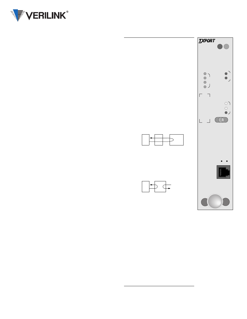
Front Panel Description
STATUS
When the green indicator is On, the
unit is powered and may be
operating normally.
When the red indicator is On, there
is a fault that exceeds alarm
thresholds or another type of unit
failure.
TD
This green indicator is On during a
mark condition on the high-speed
transmit-data line.
RD
This green indicator is On during a
mark condition on the high-speed
receive-data line.
RTS
This green indicator is On when the
request to send signal is active.
DTR
This green indicator is On when the
data terminal ready signal is active.
FAR/LOC In the FAR position, the 4051 sends
five seconds of the V.54 loop
pattern then switches to the 511
pattern.
In the middle position, the 4051
sends five seconds of V.54
loopdown code then returns to its
normal operating mode.
In the LOC position, the 4051
performs a network latching
loopback.
Activity
Indicators
These two, small recessed
indicators are just above the
supervisory connector and show
supervisory and network manager
port activity.
SUPV
The supervisory port provides
direct terminal access to control
and monitor the 4051.
NET LOS This red indicator is On during a
loss of signal from the DDS
network.
NET OOF This amber indicator is On when
the unit detects and out of frame
condition or receives OOF codes.
TST
LOOP
This amber indicator is On when
the network interface is in any loop.
TST
BERT
This indicator is On when a 511-bit
BERT is in progress.
TST ERR This indicator is On when BERT
pattern errors are detected.
DTE
Far End
DTE
Network
STATUS
4051
CSU/DSU
LOS
OOF
TD
RD
RTS
DTR
S
U
P
V
N
E
T
T
S
T
LOC
FAR
LOOP
BERT
ERR
D
T
E