Rear panel pinouts, Rear panel, Switch s1 – Verilink PRISM 4001 (CG) Configuration/Installation Guide User Manual
Page 2: Switch s2, Data port pinouts, Loops
T
R
A
N
S
P
O
R
T
®
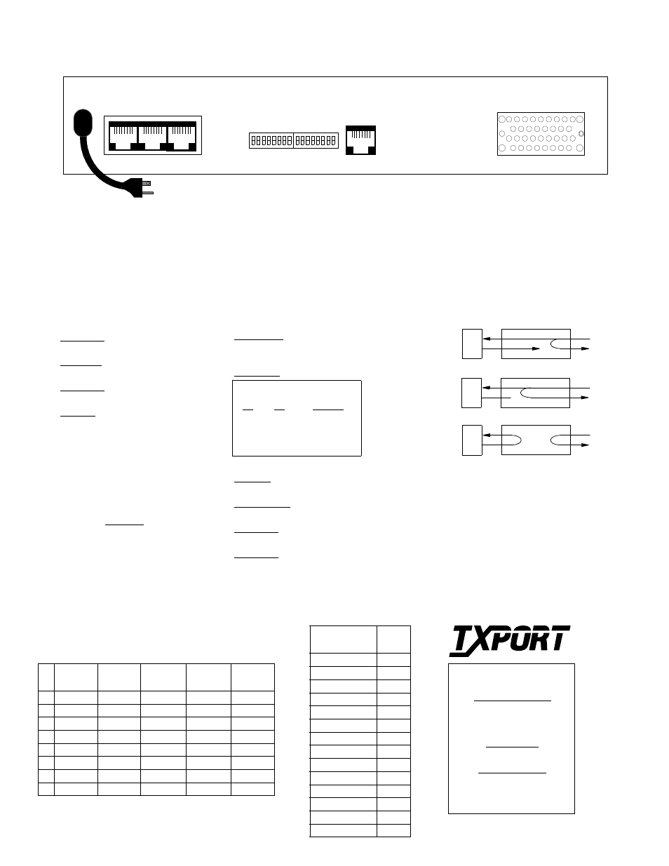
Rear Panel Pinouts
Pin
LAN
Ethernet
LAN
Token Ring
SUPV/SLIP
Terminal
SUPV/SLIP
Modem
Network
1
Data Out
DCD Out
DTR Out
Data Out
2
Data Out
CTS Out
RTS Out
Data Out
3
Data In
Data Out
Frame Gnd
Frame Gnd
4
Data In
Data Out
Data Out
5
Data In
Data In
Data In
6
Data In
Data Out
Signal Gnd
Signal Gnd
7
RTS In
CTS In
Data In
8
DTR In
DCD In
Data In
Factory defaults for all switch
settings are shown underlined.
Rear Panel
127 Jetplex Circle
Madison, Alabama 35758
Sales and Marketing
800 - 926 - 0085
205 - 772 - 3770
Returns/RMA
800 - 926- 0085, ext. 2227
Technical Support
800 - 285 - 2755
205 - 772 - 3770
Switch S1
S1 -1: Antistream timer set to 30 seconds.
Dn: Disable
Up: Enable
S1 -2: Activates the V.54 loop/unloop.
Dn: Enable
Up: Disable
S1 -3: Activates the circuit assurance.
Dn: Disable
Up: Enable
S1 -4: Establishes the loop mode.
Dn: Bidir
Up: Unidir
S1-5: Not Used
S1-6: Not Used
S1-7: Not Used
S1-8: Not Used
Switch S2
S2 - 1: Boot mode.
Dn - Switches
Up - Saved Configuration
S2 - 2: DDS mode as DDS I (56 kbps) or DDS II
(64 kbps).
Dn - 64 kbps
Up - 56 kbps
S2-5: CTS Delay.
Dn: Short
Up: Long
S2 - 6: RTS, CTS, DCD Handshake.
Dn: Force True
Up: Normal
S2 - 7: Remote/Local loops on the DTE interface.
Dn: Disable
Up: Enable
S2 - 8: DTE Alarm.
Dn: Disable
Up: Enable
S2 - 3
S2 - 4
Timing Source
Dn
Dn
Network
Dn
Up
Internl
Up
Dn
DTEl
Up
Up
Not Used
Data
Port Pinouts
Common Name
V.35
34-pin
Frame Ground
A
Transmit Data
P, S
Receive Data
R, T
Request to Send
C
Clear to Send
D
Data Set Ready
E
Signal Ground
B
Data Carrier Detect
F
Receive Clock
V, X
Terminal Timing
U, W
Transmit Clock
Y, AA
Local Loopback
J
Data Term Ready
H
Remote Loopback
BB
SUPV
SLIP
LAN
NET
V.35
115 VAC
60 HZ
S2
S1
DTE
NET
Line Loop
DTE
NET
Data Loop
V.54 Loop
DTE
NET
Local Loop
Loops