Verilink PRISM 3002 (CG) Configuration/Installation Guide User Manual
Prism 3002, Configuration guide, Front panel description
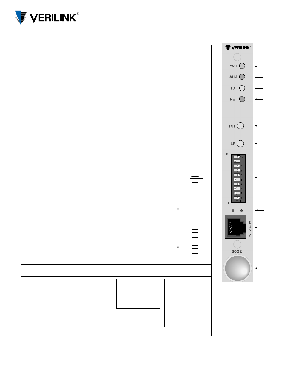
Front Panel Description
Index
Control/
Indicator
Function/Description
1
PWR
(green)
This LED lights continuously when power is applied to the unit.
2
ALM
(red)
This LED lights continuously when the unit is in an active alarm condition.
This LED blinks to show it has a duplicate NMS address detected by an 8100A.
3
TST
(3-color)
Flashing Green: The unit is transmitting loop code.
Solid Green:
BERT is on with no errors or the unit is in clear test.
Red:
BERT is on and receiving errors.
Amber:
The unit is looped.
4
NET
(3-color)
Green:
The unit is in frame sync.
Amber:
The unit is receiving a yellow alarm from the far end.
Red:
The unit is out of frame sync and/or has loss of signal.
5
TST
When this button is pushed once, the unit transmits five seconds of in-band LLB code out
to the network and performs a T1 NET BERT. Indicator TST blinks green during
transmission of the loop code. If the TST button is pushed again, the unit transmits five
seconds of in-band loop down code and returns to normal operating mode. The TST
indicator then turns off.
6
LP
When this momentary push button is pushed once, the unit activates a line loopback,
looping the network receive data back to the network, and looping the data from the DTE
ports back to the DTE. The TST indicator is amber while the unit is looped. If pushed
again, the unit clears the loop and turns off the TST indicator.
7
10-position
DIP switch
Switches S1-1 through S1-8 set the NMS address for the network
manager port. When using the 3002 with an 8100A Site
Controller, each element must have a unique unit address (see
index item 2, ALM). The 8100A Site Controller can address up to
100 units (with addresses from 1 to 100). If the unit is not
connected to a site controller, the NMS unit address should remain
at the factory default setting of 1 where Position 1 is Left and all
other positions are Right.
Switch positions S1-1 through S1-8 are used to create an 8- bit
binary code for an address in the range of 1 to 253. Switch
position S1-1 is the least significant bit (LSB) and S1- 8 is the
most significant bit (MSB). If a switch is Right, its value is 0. If
Left, its value is that shown on the left. The values are additive.
For example, to set a unit address to 5, position S1-3 (value is 4)
and position S1-1 (value is 1) would be set Left for a unit address
of 5 (4+1). All other positions would be set Right. If all the
switches are Right, the address is 1.
8
These small, recessed red LEDs indicate supervisory and network manager activity from
the 3002.
9
SUPV
The supervisory port provides
direct terminal access for
control and gathering status and
facility performance data.
Tables showing the port rate
and pinout are given on the
right.
10
Extractor/cardlock
Left
Right
12
3
4
5
6
78
9
10
SUPV Rate
SUPV Rate
128
64
32
16
8
4
2
1
LSB
M
S
B
Bin
ary
v
alu
e
s
0
0
0
0
0
0
0
0
SUPV Port Pinout
Pin
Data Terminal Ready Out 1
Ready to Send Out
2
Frame Ground
3
Data Out
4
Data In
5
Signal Ground
6
Clear to Send In
7
Data Carrier Detect In
8
SUPV Port Rate S1-9
S1-10
1.2 kbps
Left
Left
2.4 kbps
Right Left
9.6 kbps
Right Right
19.2 kbps
Left
Right
PRISM 3002
Configuration Guide
45-00121
4.0
Front Panel
1
2
3
4
5
6
7
9
8
10