Verilink Ethernet Token Ring (CG) Configuration/Installation Guide User Manual
Ethernet/token ring card installation guide
Part Number 45-00092
Rev 2.0
Ethernet/Token Ring Card
Installation Guide
This installation guide contains the procedure to configure and install an Ethernet or Token Ring card into a 3100 series, 4100
series, or an 8100A unit.
Step 1:
[Ethernet card only] Configure the ethernet card by setting the jumper (J1) and the dual in-line package (DIP)
switches (S1). Refer to bottom figure for location identification. Refer to the following table for setting positions.
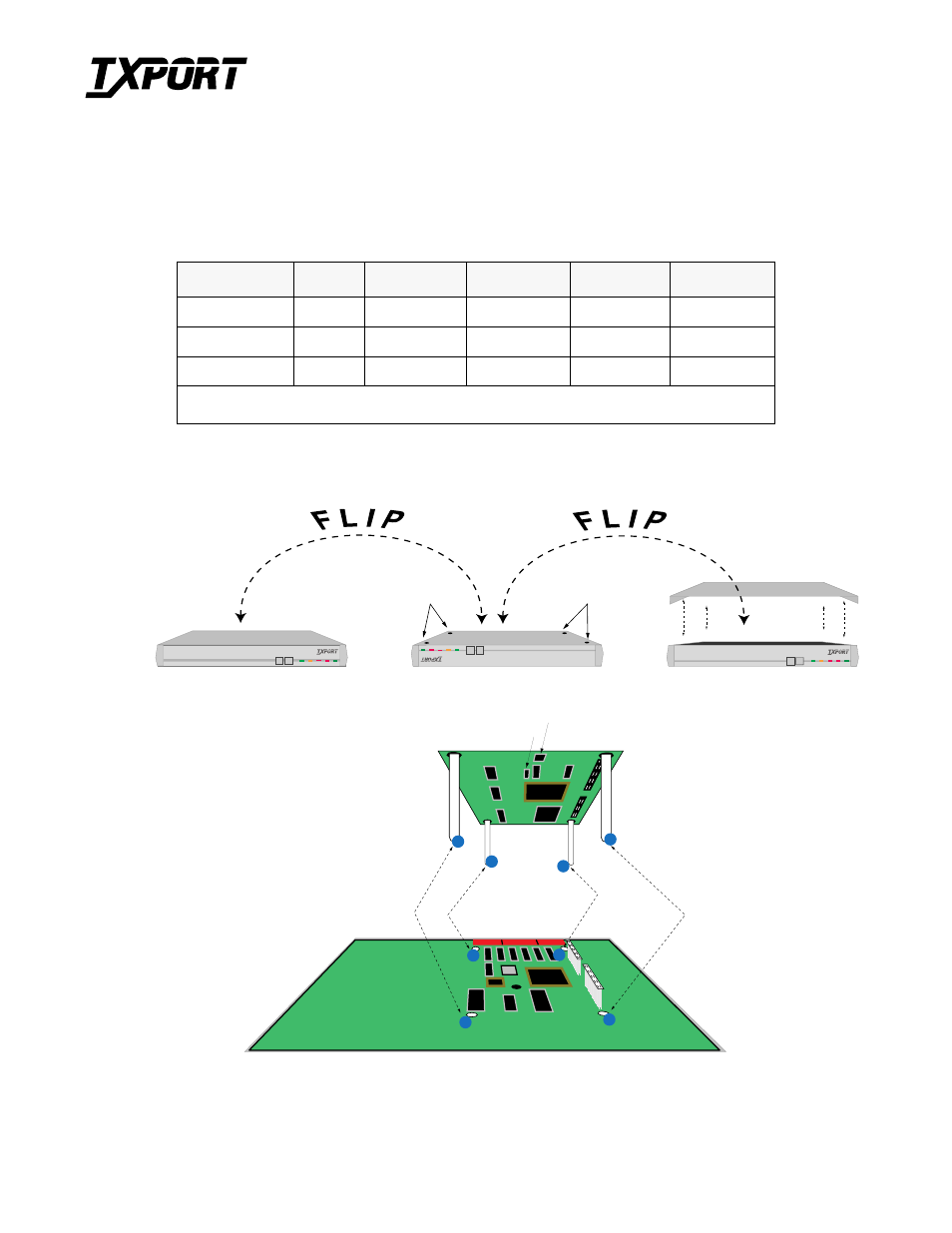
Step 2:
Disconnect power to the unit. Flip the unit and place it on a flat surface. Remove the four screws with a Phillips
head screwdriver. Then, flip the unit back to the upright position. Gently remove the top cover to expose the main
circuit board.
Step 3:
Insert the plastic stand-offs on the card into the main circuit board. as shown in the figure below.
Step 4:
Once the board is firmly connected, place the cover back on the unit, flip the unit, and reinsert the four screws.
Unit
J1
S1-1 (A16)
S1-2 (A17)
S1-3 (A18)
S1-4 (A19)
3100 Series
1-2
Off
Off
On
On
4100 Series
2-3
Off
Off
On
On
8100A
2-3
Off
On
Off
On
S1 settings have four different interpretations:
On = Closed = Up = 0
Off = Open = Down = 1
PRISM 3101
TEST
LOOP
TEST
LOOP
NET
ALARM POWER
T
R
A
N
S
P
O
R
T
PRISM 3101
TEST
LOOP
TEST
LOOP
NET
ALARMPOWER
T
R
A
N
S
P
O
R
T
s c r e w s
s c r e w s
PRISM 3101
TEST
LOOP
TEST
LOOP
NET
ALARM POWER
T
R
A
N
S
P
O
R
T
A
B
C
D
A
B
C
D
S1, S2 and S3
switches
J1
S1
T
R
A
N
S
P
O
R
T
®