Chassis address selection, 1250 controls and indicators, 1557 chassis addresses – Verilink APS Card Replacement (CG) Configuration/Installation Guide User Manual
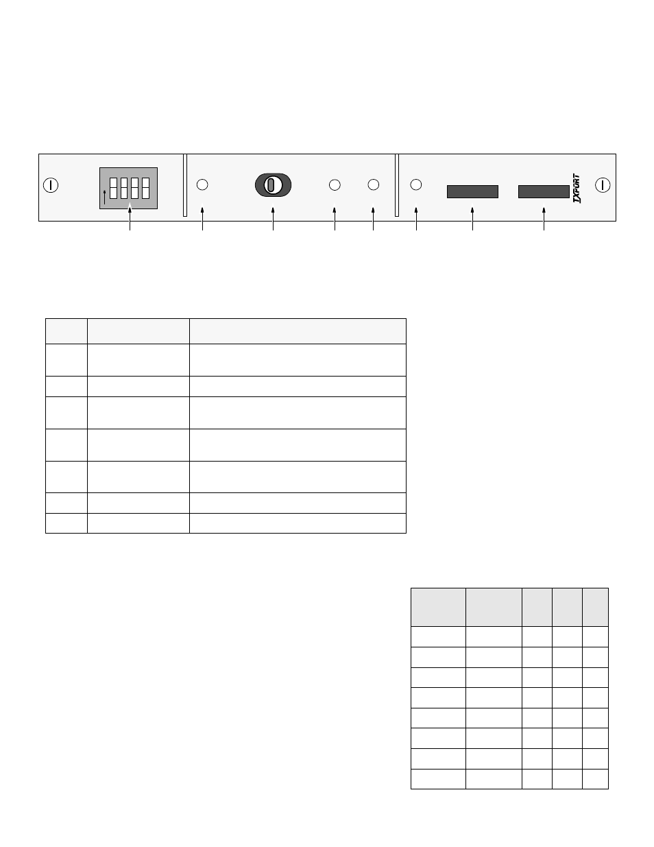
Page 3: 1250 front view, Figure 2 power and alarm card functions
1250 Controls and Indicators
Index
Indicator
Description
1
CHASSIS ADDRESS
DIP switch which provides up to 8 chassis addresses
(refer to the instructions below).
2
POWER
Indicates that power is being supplied to the unit.
3
NORMAL/SILENT
Normal enables the ACO (Alarm Cut Off).
Silent disables the ACO.
4
ACO
The Alarm Cut Off LED indicates that the alarm
relay contacts are disabled.
5
ALARM
This LED indicates that an APS shelf alarm has
occurred.
6
FUSE ALARM
This LED indicates that a bus fuse has blown.
7
3 AMP GMT
Two 3 Amp fuse for power source A/B.
1557 Chassis Addresses
Chassis
Number
Base
Address
S2
S3
S4
1
0 to 27
0
0
0
2
32 to 59
0
0
1
3
64 to 91
0
1
0
4
96 to 123
0
1
1
5
128 to 155
1
0
0
6
160 to 187
1
0
1
7
192 to 219
1
1
0
8
224 to 251
1
1
1
Chassis Address Selection
Each APS chassis must be assigned a block of addresses for its 1557 APS
cards so that the 1559 APS Manager may communicate with them. The DIP
switch located on the front panel of the 1250 Alarm and Power Card is used to
provide up to 8 chassis addresses. These addresses are used by the APSM to
poll and send commands to the 1557 cards.
Three out of the four switches (S2, S3, and S4) are set to one of the 8 possible
address codes as shown in the table to the right. The DIP switch positions are
number S1 through S4, with S1 on top and S4 on bottom. Note that S1 is not
used and must remain open to 0, which is the left switch position.
The first unit address (1557 card) in the chassis is the base address plus 1. For
example, if S2, S3, and S4 were all set to 0, the first unit address in the chassis
would be ‘1’ (0 + 1).
AL
ARM
&
PO
WE
R
CH
AS
S
IS
ADDRES
S
1
2
3 4
O
N
1
2
3
–
PO
WER
NO
RM
AL
S
ILENT
AC
O
AL
AR
M
FU
S
E
ALA
R
M
A
B
3 AM
P
GM
T
12
50
TRANSPORT
®
1
2
3
4
5
6
7
7
1250 Front View
NOTES: 1250 cards that are Rev. 2.63 or
higher add the capability to maintain alarm
card functions (front panel indicators, switch
functions, and relay operation) even when
Fuse A and B are open. This is possible
because these cards have the alarm circuitry
wired to the ‘hot’ side of the incoming A and
B external power source(s). In early revi-
sions, the 1250 alarm functions were only
operational if one or more of the front panel
fuses were functional (not blown).
Earlier versions of the 1250 card were called
1555P cards. The primary functions of both
cards are the same.
Figure 2
Power and Alarm Card Functions