Verilink 4010 Standalone (CG) Configuration/Installation Guide User Manual
Prism 4010, Front panel description, Switch sw1
T
R
A
N
S
P
O
R
T
®
PRISM 4010
45-000135
1.0
Configuration Guide (Standalone Version)
2
4
5
6
7
8
9
10
11
3
PRISM 4010
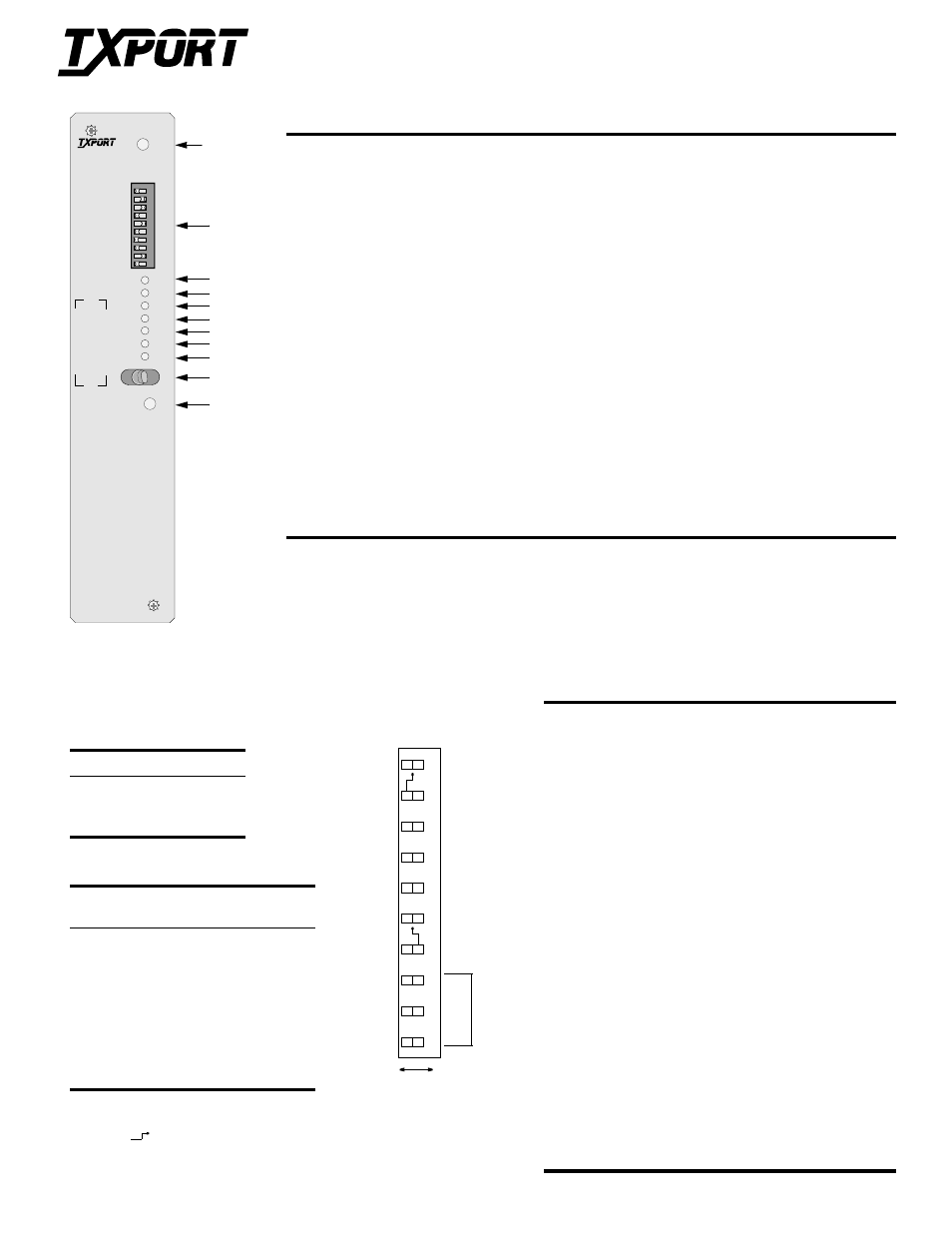
Front Panel
Front Panel Description
Pins
Description
1
In Service - This three-color IN SERVICE LED indicates the DDS loop receiver’s operating status as follows.
Green:
Indicates DDS signal at the receiver (either customer data or zero suppression).
Amber: Indicates DDS signal is still present, but received data is idle or out of service.
Red:
Indicates an insufficient signal for the DDS receiver to operate properly.
2
Switch SW1 - This 10 - position LED switch is described below.
3
TXD - This green transmit-data LED lights when the data lead is a mark and is off when the data lead is a space.
Therefore, the LED varies from full intensity to off, depending on the relative number of marks and spaces.
4
RXD - This green receive-data LED lights when the data lead is a mark and is off when the data lead is a space.
Therefore, the LED varies from full intensity to off, depending on the relative number of marks and spaces.
5
RTS - This green request-to-send LED lights when circuit CA is in the ON state at the DSU interface.
6
CTS - This green clear-to-send LED lights when circuit CB is in the ON state at the DSU interface.
7
DCD - This green receive-line-signal-detector LED lights when circuit CF is in the ON state at the DSU interface.
8, 9
V.35 and 232 - The green V.35 LED is on when the DTE electrical interface is set to V.35. The green 232 LED is
on when the interface is set to RS-232. If neither light is on, the configuration switches are set incorrectly.
10
Test Switch - This three- position switch operates as follows.
The LOC position places the unit in a local-loop mode. Data from the DTE is looped back to the DTE. Data from
the network is looped back to the network.
The FAR position initiates an automated V.54 remote loop and BERT sequence of assigned data channels. The
TEST LED is green if the test is successful (the far-end unit loops and returns the data error free with the V.54
code). If errors are detected, the TEST LED is red.
The center position deactivates the loop codes for normal operation.
11
LOOP TEST - This LED remains amber if there is a local loop or a remote loop. The LED turns red if the V.54
BERT test fails or green if the V.54 BERT test passes.
6
5
4
3
1
7
9
8
2
Data Polarity
Circuit Assurance
RTS/CTS Control
Data Polarity
Circuit Assurance
RTS Normal Delay
Channel
B
it R
ate
A
V.54 Loop
V.54 Loop
Internal Clock
Line Clock
Inverted
Normal
Off
On
Enabled
Inhibited
RTS/CTS Control
RTS Control On
RTS-to-CTS
RTS-to-CTS
Delay Normal
The symbol
indicates that the switch pointed to does not function un-
less the opposite end of the arrow is in the position shown. For example,
SW1 -5 does not function unless SW1 - 4 is in the B position.
10
Rate
(kbps)
SW1-1 SW1-2 SW1-3
RTS - to -
CTS Delay
2.4
B
B
B
8 ms
4.8
A
B
B
4 ms
9.6
B
A
B
2 ms
19.2
A
A
B
1 ms
28
B
B
A
0.8 ms
38.4
A
B
A
0.5 ms
56
B
A
A
0.4 ms
64
A
A
A
0.3 ms
Switch SW1
Pins Description
1 - 3 Channel Bit Rate Select - These three positions select the
channel bit rate (refer to the table on the right). The RTS-to-
CTS delays are multiplied by two when SW1-10 is in the B
position.
4
Line Clock - This position selects either an internal clocking
source or a loop timing source from the received data.
5
Internal Clock - This position selects either the DSU external
clock input or the crystal oscillator as the clocking source. It is
applicable only if SW1-4 is in the B position.
6
V.54 Loop Operation - This position enables or inhibits V.54
loop operation.
7
Data Polarity - This position determines whether data bits are
inverted. In the A position, marks equals pulses. In the B
position, spaces equal pulses. Receipt of OOF, OOS, idle, or
loop codes forces the DSU data to all marks (A position) or
spaces (B position).
8
Circuit Assurance - On allows the status of CF (receive line
signal detector) and CA (request to send) to control the output
CB (clear to send). If either CA or CF is Off (A position), CB is
Off. If CA and CF are On (B position), CB is On.
9
RTS /CTS Control - In the B position, CTS is forced On
regardless of the RTS input status. In the A position, delays are
determined by SW1-10.
10
RTS-to-CTS Delay - In the A position, the RTS-to-CTS delay is
as shown in the bit rate table of the diagram. In the B position,
the delays shown are multiplied by two.
B
Delay
×
2
Rate (kbps)
SW1- 4 SW1- 5
Network (slave) A
n /a
Master
B
A
External
B
B
1
LOOP TEST
LOC
FAR
TSD
RXD
RTS
CTS
DCD
V.35
232
1 2 3 4 5 6 7 8 9 10
SW1
INSERVICE
4010
DDS
CSU\DSU
T
R
A
N
S
P
O
R
T