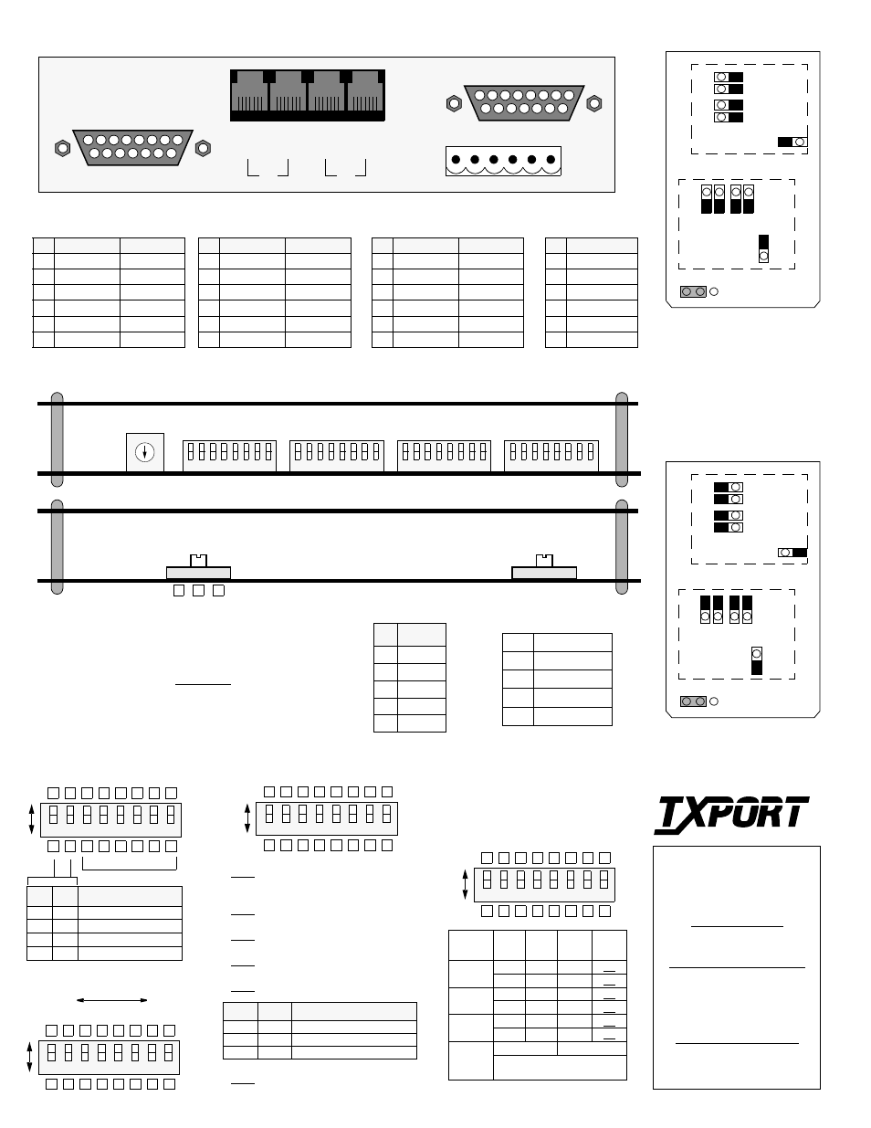
Po wer/ alarm, Circuit board view, Address switch s7 – Verilink 2048 (CG) Configuration/Installation Guide User Manual
Page 2: User/ptt connection, J4 e q p t, P2 n e t, Configuration switch s6, Supervisory port, Configuration switch s5, Equipment/network connection
S1
Pos 1 Pos 2 Configuration Mode
Dn
Dn
Boot from switches
Dn
Up Download from manager
Up
Dn
Boot from RAM
Up
Up
Boot from ROM
NOTE: For future reference, all DIP switches are
provided with upper and lower boxes to check
according to the particular user selection. Factory
default settings are shown underlined.
NOTE: On all switches, the ‘Up’ or ‘1’ position is
OPEN and the ‘Dn’ or ‘0’ position is CLOSED.
Configuration Switch S4
8
6
5
4
3
2
1
Dn
Up
7
Circuit Board View
MSB
LSB
Address Switch S7
12
8
64
32
16
8
4
2
1
2048 PMU Rear Panel (with DB15)
P
o
wer/
Alarm
6
1
1
6
User/PTT Connection
Switch S5
1
8
7
6
5
4
3
2
Switch S7
1
8
7
6
5
4
3
2
Switch S4
1
8
7
6
5
4
3
2
TxPORT
127 Jetplex Circle
Madison, Alabama 35758
Customer Service
800-926-0085, ext. 227
Product Technical Support
(8 a.m. to 5 p.m. Central)
800-285-2755 or
205-772-3770
Emergency After Hours
Support: 800-285-2755
INET: [email protected]
T
R
A
N
S
P
O
R
T
®
5
1
7
9
0
6
8
2
3
4
Switch S6
1
8
7
6
5
4
3
2
Switch SW2
IN
OU
T
USER
8
15
1
9
J
4
E
Q
P
T
1
9
8
15
P
2
N
E
T
6
1
IN
OU
T
PT
T
Switch S1: Sets the output signal level (LBO) of transmitted data. The
PTT should provide the proper setting. Check the box which corresponds
to your LBO setting. If unsure of the exact setting, then slide to 0 dB.
Spares
1.2
kb/s
2.4
kb/s
9.6
kb/s
19.2
kb/s
SUPV - 1
- 2
Dn
Dn
Up
Up
Dn
Up
Dn
Up
User - 3
- 4
Dn
Dn
Up
Up
Dn
Up
Dn
Up
PTT - 5
- 6
Dn
Dn
Up
Up
Dn
Up
Dn
Up
Nat’l - 7
Bit
- 8
Dn (0) = Pass Up (1) = Select
Select Dn (0) or Up (1) for nat’l
bit if S6-7 is set to ‘Select’
Super
v
is
ory
Super
v
is
ory
Us
er
NM
S
Us
er
NM
S
PT
T N
M
S
PT
T N
M
S
Na
tiona
l bit
Na
tiona
l bit
S5-1: Sets the BERT data polarity to a ‘1’ or ‘0’.
Down - 1
Up - 0 (inverted)
S5-2: IBLC - Enables the inband 5-bit loop up
code and 3-bit loop down code detection.
Down - Enabled
Up - Disabled
S5-3: Matches the PMU to the line framing used.
Down - CAS
Up - CCS
S5-4: Sets the network line code for the E1 signal.
Down - HDB3
Up - AMI
S5-5: Enables the CRC4 framing format.
Down - Enabled
Up - Disabled
S5-8: Enables CRC4 Insert on the network side.
Down - Disabled
Up - Enabled
Pos 6
Pos 7
AIS/Keep Alive Selection
Dn
Dn
AIS is unframed all ones
Dn
Up
AIS is framed all ones
Up
Dn
Line Loopback (LLB)
Pos
Nat’l Bit
1
1
2
2
3
3
4
4
5
5
8
6
5
4
3
2
1
Dn
Up
7
8
6
5
4
3
2
1
Dn
Up
7
8
6
5
4
3
2
1
Dn
Up
7
Configuration Switch S6
J1
2
J1
3
J1
4
J1
5
J1
6
J4
J5
J6
J7
J8
J1
2
J1
3
J1
4
J1
5
J1
6
J4
J5
J6
J7
J8
75 ¾ Jumper Configuration
120 ¾ Jumper Configuration
Switch SW2
1 /6 Not
Used
2
Signal Ground
3
Data Out
4
Data In
5
Signal Ground
Supervisory Port
(front panel)
Configuration Switch S5
Pin
EQPT RJ48
NET RJ48
1
Data Out
Data In
2
Data Out
Data In
3/6
Not
Used Not
Used
4
Data In
Data Out
5
Data In
Data Out
7/8 Chassis
Gnd Chassis
Gnd
Pin EQPT DB15 NET DB15
1
Data
In Data
Out
2
Frame Ground Frame Ground
3
Data Out
Data In
4
Frame Ground Frame Ground
9
Data
In Data
Out
11
Data Out
Data In
Equipment/Network Connection
Pin
Function
1
48 VDC Return
2
Signal Ground
3
-48 VDC
4
Frame Ground
5
Alarm Contact
6
Alarm Common
Power/Alarm
Pin NMS In/Out
NMS Out
1
Not Used
Not Used
2
Signal Gnd
Signal Gnd
3
Data Out
Data Out
4
Data In
Not Used
5
Signal Gnd
Signal Gnd
6
Not Used
Not Used
S2
Switch S2: This switch swaps the DTE
Tx/Rx pair for either normal stand-alone
use or for chassis nest mount use.
-15 -7.5 0
NORM
RACK
Front
Equipment
Equipment
Front
Network
Network
J18
NO
NC
Rear
J18
NO
NC
Rear
Alarm Relay: Pin 5 on the
Power /Alarm terminal strip is
configured to operate either in
a normally open (NO) or a
normally closed (NC) mode as
determined by Jumper J18.