2010 rear panel – Verilink 2010 Standalone (CG) Configuration/Installation Guide User Manual
Page 2
TxPORT Customer Service
127 Jetplex Circle
Madison, Alabama 35758
Customer Service Returns:
800- 926-0085, ext. 227
Product Technical Support
(8 a.m. to 5 p.m. Central)
800-285- 2755 or
205- 772-3770, ext. 255
Emergency After Hours:
800-285- 2755
Manager: 205-603-2194
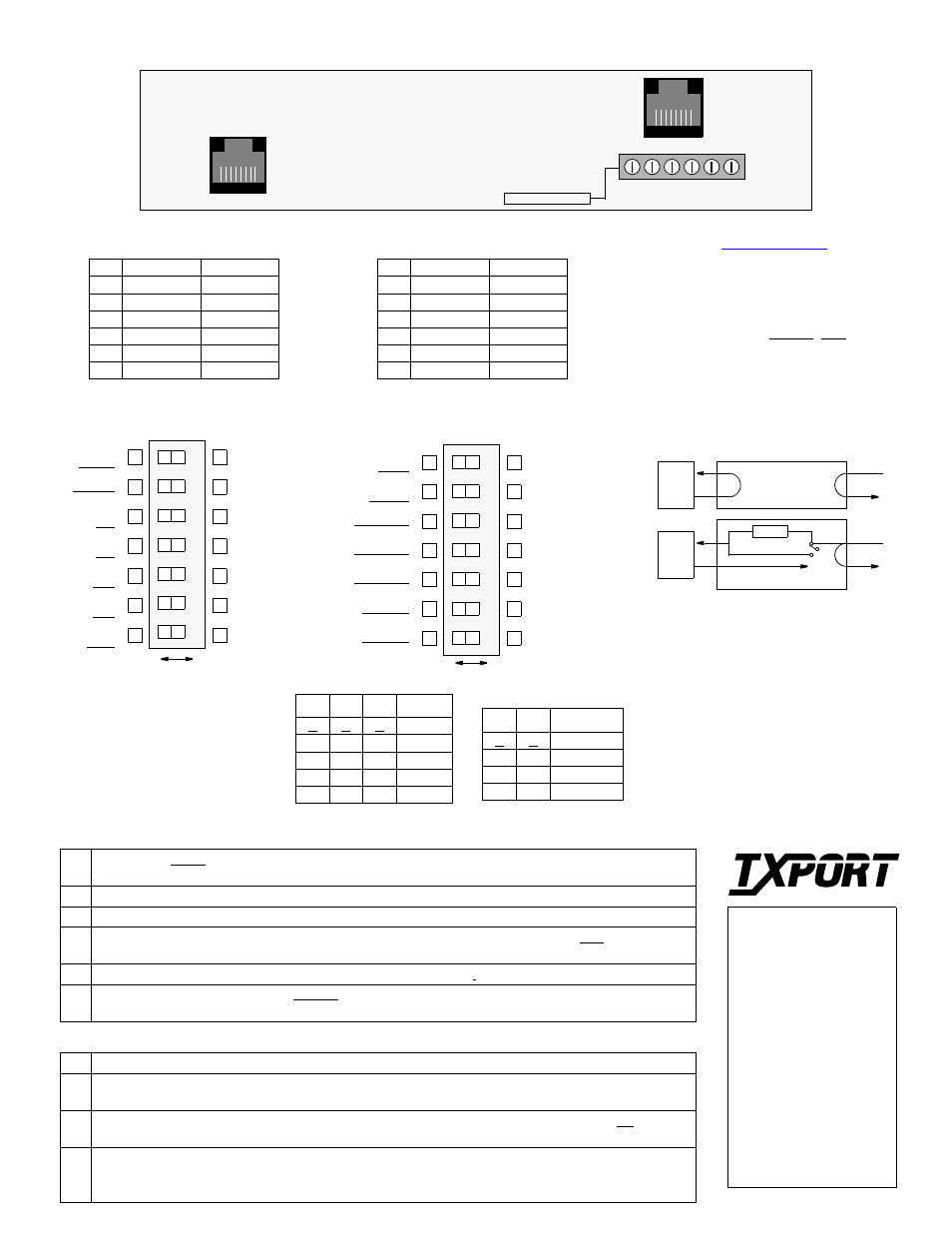
2010 Rear Panel
T
R
A
N
S
P
O
R
T
®
Switch S2 (front panel)
PRM
7
6
5
4
3
2
1
NET LBO
NET LBO
DTE ALBO
DTE ALBO
DTE ALBO
PRM
AIS
AIS
DTE ALBO
NET LBO
DTE ALBO
DTE ALBO
NET LBO
B
A
1 ESF Mode: 54016 - the unit responds only to 54016 CSU messages. T1.403 mode - the unit responds to
ANSI loop/unloop commands and generates a PRM every second, but will not respond to 54016 messages.
2
Network Line Coding: Sets the NET line coding (including conversion).
3 DTE Line Coding: Sets DTE line coding (including conversion)
4 Network Line Framing: Sets the CSU to the framing of the network line. In the ESF mode, the unit
responds to all T1.403 or 54016 messages.
5
DTE Line Framing: Sets the CSU to the framing of the DTE line.
7
Density (zero suppression mode): Enabled allows ones density control after 15 successive zeros from the
DTE (per TR62411). Disabled ignores density control and allows 175 zeros to pass towards the network.
S2 -1 S2 -2 Attenuation
A
A
0 dB
A
B
-7.5 dB
B A - 15.0
dB
B B - 22.5
dB
S2 - 3 S2 - 4 S2 - 5 Distance
A
A
A
0 -133
B
B
B
134- 266
A
B
B
267- 399
B
A
B
400- 533
A
A
B
534- 655
Power: The unit is operated from 20 -
56 VDC (80 mA at -24 VDC or 45
mA at -48 VDC).
Alarm: The alarm relay contacts are
configured for ‘normally open’ or
‘normally closed’ operation, depend-
ing on the alarm relay jumper setting
(requires optional alarm card).
Pin DTE
NET
1
Data Out
Data In
2
Data Out
Data In
4
Data In
Data Out
5
Data In
Data Out
7
Frame Gnd
Frame Gnd
8
Frame Gnd
Frame Gnd
DTE
NET
AIS
Remote Loopback
Loopbacks
DTE
NET
Local Loopback
The 2010 can be looped remotely by generat-
ing towards it a standard CSU line loopback
code (00001 repeating for Š 5 seconds,
framed or unframed). Once looped, the re-
ceived signal from the T1 facility (NET IN) is
regenerated and transmitted back to the T1 fa-
cility (NET OUT).
The 2010 can be unlooped remotely by gen-
erating towards it a standard CSU line unloop
code (001 repeating for Š 5 seconds, framed
or unframed). The 2010 responds to FDL
loop and unloop command messages.
Switch S1
1-2 Network LBO: Sets the network signal level of data transmitted towards the T1 facility. Refer to the table.
3-5 DTE ALBO: Sets the DTE line build out transmit value towards the customer equipment. The value
should match the cable length from the CSU DTE port to the attached equipment. Refer to the table above.
6 AIS Enable: Enables sending an alarm indication signal during an active payload loopback. A - generate
AIS to DTE during remote loop; B - Pass received network signal to DTE.
7 PRM Enable: Enables sending a PRM during an AIS. If the unit detects loss of sync from the DTE, an
unframed all ones signal is generated to the T1 facility. If Switch S2-6 is set to generate AIS and Switch
S1-1 is set for T1.403 operation, the unit interrupts the AIS signal with a PRM once a second.
Switch S2
Network LBO
DTE ALBO
RJ48C Interface
NOTE: The ‘A’ position is the fac-
tory default for all switch settings.
If a particular user configuration
requires that a switch be placed in
the ‘B’ direction, then mark this
sheet for future reference.
Pin DTE
NET
1
Data In
Data Out
2
Frame Gnd
Not Used
3
Data Out
Data In
4
Frame Gnd
Not Used
9
Data In
Data Out
11
Data Out
Data In
DB15 Interface (option)
Power and Alarm
Enable
Generate
Disable
Pass Data
Density
DTE framing
NET framing
DTE code
NET code
Op Mode
Density
DTE framing
NET framing
DTE code
NET code
Op Mode
7
6
5
4
3
2
1
Switch S1 (front panel)
Disabled
D4
D4
B8ZS
B8ZS
T1.403
Enabled
ESF
ESF
AMI
AMI
54016
B
A
Not Used
Not Used
DTE
8
1
8
1
NET
1+
V
2G
N
D
3–
V
4F
R
M
G
N
D
5A
L
M
6A
L
M
C
O
M
(DB1
5
A
v
ail)
1
6
Op
tion
(DB1
5
A
v
ail)
Op
ti
o
n