Circuit board view, Chassis connections, Nc no – Verilink 2000 (1051-2 Chassis) (CG) Configuration/Installation Guide User Manual
Page 2: Configuration switch s3 alarm relay mode
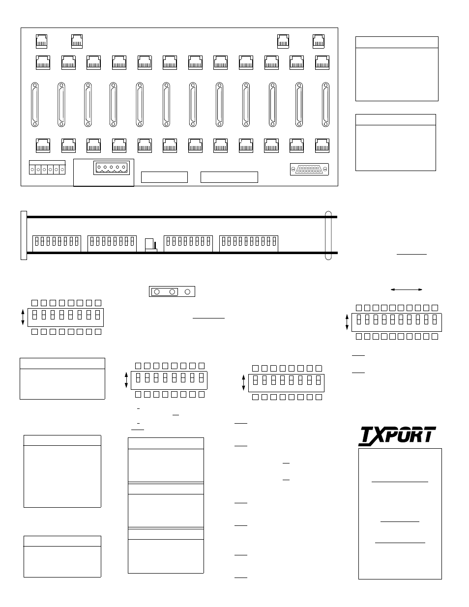
Chassis Connections
Pin
T1 DTE T1 NET
1
Data Out
Data In
2
Data Out
Data In
3
Not Used
Not Used
4
Data In
Data Out
5
Data In
Data Out
6
Not Used
Not Used
7, 8
Chassis Gnd
Chassis Gnd
Pin
NMS In
NMS Out
1
Not Used
Not Used
2
Signal Gnd
Signal Gnd
3
Data Out
Data Out
4
Data
In Not
Used
5
Signal Gnd
Signal Gnd
6
Not Used
Not Used
T1 DTE
1
2
3
4
5
6
7
8
9
10
11
12
( B )
NMS
IN
( B )
NMS
OUT
12
High Speed DTE
11
10
9
8
7
6
5
4
3
2
1
T1 NET
TB2
TB1
ENET
( A )
NMS
IN
( A )
NMS
OUT
TB1
TB2
TxPORT 1051 Chassis Rear View (V.35 version also available)
Switch S3
1
8
7
6
5
4
3
2
NOTE: For future reference, all
DIP switches are provided with
upper and lower boxes to check
according to the particular user
selection. Factory default set-
tings are shown underlined.
This 3-pin jumper straps the ACO alarm contact.
Move the jumper to the left for normally open
operation (closes on alarm) or to the right for
normally closed operation (opens on alarm).
8
6
5
4
3
2
1
Dn
Up
7
NC
NO
Network LBO: Sets the output signal
level of the transmitted data.
S3-1
S3-2
Line Build Out
Dn
Dn
0 dB
Dn
Up
-7.5 dB
Up
Dn
-15.0 dB
Up
Up
-22.5 dB
DTE LBO: The output level of the
DTE interface should match the cable
length from the CSU DTE port to the
attached equipment.
S3- 3
S3- 4
S3- 5
Distance
Dn
Dn
Dn
0 -110
Dn
Dn
Up
110-220
Dn
Up
Dn
220-330
Dn
Up
Up
330-440
Up
Dn
Dn
440-550
Up
Dn
Up
550-655
Up
Up
Dn
> 655
Up
Up
Up
Square
Clock: Sets the CSU’s timing source
for data transmitted toward both the
network and DTE.
S3- 6
S3- 7
S3- 8
Source
Dn
Dn
Dn
Normal
Up
Dn
Dn
Internal
Up
Up
Dn
Network
Up
Up
Up
DTE
Circuit Board View
Configuration Switch S3
Alarm Relay Mode
Alarm
Relay
Switch S4
1
8
7
6
5
4
3
2
Switch S5
1
8
7
6
5
4
3
2
Switch S6
1
8
7
6
5
4
3
2
9 10
S4-1: T1.403 PRM:
Down - enabled
Up - disabled
S4-2: Audible Alarm (buzzer)
Down - disabled
Up - enabled
Dn
Up
Dn
Up
S4- 3 S4-4
Boot Mode
Dn
Dn
Boot from Switches
Dn
Up
Boot from RAM
Up
Dn
Boot from Manager
Up
Up
Boot from ROM
S4-5 S4-6 SUPV Port Rate
Dn
Dn
19200 bps
Dn
Up
9600 bps
Up
Dn
2400 bps
Up
Up
1200 bps
S4-7 S4-8 NMS Port Rate
Dn
Dn
19200 bps
Dn
Up
9600 bps
Up
Dn
2400 bps
Up
Up
1200 bps
S5-1: Network Line Framing - matches the CSU to
the framing of the network line.
Down - ESF
Up - D4
S5-2: DTE Line Framing - Matches the CSU to the
framing of the DTE line.
Down - ESF
Up - D4
S5-3: Network Line Coding
Down - AMI
Up - B8ZS
S5-4: DTE Line Coding
Down - AMI
Up - B8ZS
S5-5: Network AIS - Sets the all ones signal sent
out to the network in a keep alive condition.
Down - Unframed
Up - Framed
S5-6: Network Keep Alive Mode - Selects the ac-
tion to occur on a DTE loss of signal.
Down - Send AIS
Up - Loop NET data in to
NET data out
S5-7: ESF CRC Mode - Regenerates the CRC
code or passes the CRC code through unchanged.
Down - Regenerate
Up - Pass
S5-8: ESF FDL Mode - Terminates the received
data link in the CSU or passes it through unchanged.
Down - Terminate
Up - Pass
MSB
LSB
S6-1: Zero Suppression (ones density):
Down - Enable
Up - disable
S6-2: Maintenance Reset
Down - Off
Up - On
S6-3 to S6-10: The NMS address is defined
with this 8-bit binary code. The factory
default value is 1, which is S6-10 in the up
position and S6-3 through S6-9 down.
Dn
Up
1
2
4
8
16
32
64
128
Configuration Switch S6
Configuration Switch S4
Configuration Switch S5
127 Jetplex Circle
Madison, Alabama 35758
Sales and Marketing
800-926-0085
205-772-3770
Returns/RMA
800-926-0085, ext. 2227
Technical Support
800-285-2755
205-772-3770
T
R
A
N
S
P
O
R
T
®
8
6
5
4
3
2
1
7
8
6
5
4
3
2
1
7
8
6
5
4
3
2
1
7
9 10
1
2
3
4
5
6
7
8
9
10
11
12