Verilink 1555 (CG) Configuration/Installation Guide User Manual
Page 2
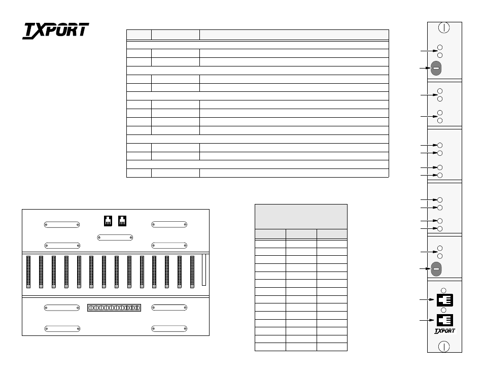
1050 APS Chassis Rear View
STATUS
ALARMS
UNIT A
1555P
UNIT A
UNIT B
FORCE A
NORM
FORCE B
FAULT
UNIT A
UNIT B
UNIT A
UNIT B
FACILITY
TX
RX
EQPT
TX
RX
UNIT B
FACILITY
TX
RX
EQPT
TX
RX
LOOP
UNIT A
UNIT B
LOOP A
NORM
LOOP B
T-VIEW
A
B
1555P Controls and Indicators
Index
Indicator
Description
STATUS
1
UNIT A / B
Indicates the current path.
2
FORCE
‘Forces’ selection to Path A or B. NORM is used for software control.
ALARMS
3
UNIT A / B
Indicates that a path is in an alarm condition.
4
FAULT
Indicates that the path is experiencing a fault (an error or failed condition).
FACILITY
5
FACILITY TX
Indicates that the signal is being transmitted toward the network.
6
FACILITY RX
Indicates that the signal is being received from the network.
7
EQPT TX
Indicates that the equipment is transmitting a signal toward the network.
8
EQPT RX
Indicates that the equipment is receiving a signal from the network.
LOOP
9
LOOP A/B
Indicates that the 1555P is in a loopback mode on Path A/B.
10
LOOP SELECT
Select switch used to select loop for Path A/B.
T-VIEW
11
T-VIEW A/B
Local service port for Path A/B.
1
3
4
5
7
5
7
9
10
11
11
6
8
6
8
2
J5
J6
J7
J1
J2
C14 C13 C12 C11 C10 C9
C8
C7
C6
C5
C4
C3
C2
C1 C15
J8
J9
J3
J4
36
35
2
1
TB1
P1
P2
36
35
2
1
36
35
2
1
36
35
2
1
36
35
2
1
36
35
2
1
36
35
2
1
36
35
2
1
36
35
2
1
36
35
2
1
36
35
2
1
36
35
2
1
36
35
2
1
36
35
2
1
Pinouts for J1 -J4 & J6-J9
(50-Pin Miniature
Female Connector)
Circuit #
Tip
Ring
1
Pin 1
Pin 26
2
Pin 2
Pin 27
3
Pin 3
Pin 28
4
Pin 4
Pin 29
5
Pin 5
Pin 30
6
Pin 6
Pin 31
7
Pin 7
Pin 32
8
Pin 8
Pin 33
9
Pin 9
Pin 34
10
Pin 10
Pin 35
11
Pin 11
Pin 36
12
Pin 12
Pin 37
13
Pin 13
Pin 38
14
Pin 14
Pin 39
T
R
A
N
S
P
O
R
T
®
TxPORT Customer Service
127 Jetplex Circle
Madison, Alabama 35758
Customer Service Returns:
800 -926-0085, ext. 227
Product Technical Support
(8 a.m. to 5 p.m.)
800-285 -2755 or
205 -772 -3770, ext. 255
After Hours Hot Line:
205-551-7538
T
R
A
N
S
P
O
R
T
®