Nms connections, Network and dte connections, Alarm connections – Verilink 1051-2 Chassis (CG) Configuration/Installation Guide User Manual
Page 2: External clock connections, High-speed dte connections
T1
NET
1
T1
NET
2
T1
NET
3
T1
NET
4
T1
NET
5
T1
NET
6
T1
NET
7
T1
NET
8
T1
NET
9
T1
NET
12
ENET
T1
NET
10
T1
NET
11
1 2 3 4 5
1 2 3 4 5 6
2.4 AMPS
HIGH
SPEED
DTE
12
HIGH
SPEED
DTE
11
TB2 -
HIGH
SPEED
DTE
10
HIGH
SPEED
DTE
9
HIGH
SPEED
DTE
8
HIGH
SPEED
DTE
7
HIGH
SPEED
DTE
6
HIGH
SPEED
DTE
5
HIGH
SPEED
DTE
4
HIGH
SPEED
DTE
3
HIGH
SPEED
DTE
2
HIGH
SPEED
DTE
1
T1
NET
7
T1
NET
8
T1
NET
9
T1
NET
12
T1
NET
10
T1
NET
11
T1
NET
1
T1
NET
2
T1
NET
3
T1
NET
4
T1
NET
5
T1
NET
6
NMS A & NMS B, IN AND OUT, ARE NON-TELECOM (T1) CONNECTORS
Les portes d'entree/sortie NMS A & NMS B sont des connecteurs non-telecommunication (T1)
( A )
NMS
OUT
( A )
NMS
IN
( B )
NMS
OUT
( B )
NMS
IN
TB1
1 - EXT CLK
2 - EXT CLK
3 - ALARM RING
4 - ALARM TIP
5 - SIG GND
1 - +48V RTN ( B )
2 - FRAME GND
3 - -48V IN ( B )
4 - -48V IN ( A )
5 - SIG GND
6 - +48V RTN ( A )
TB2
TB1 -
TB2
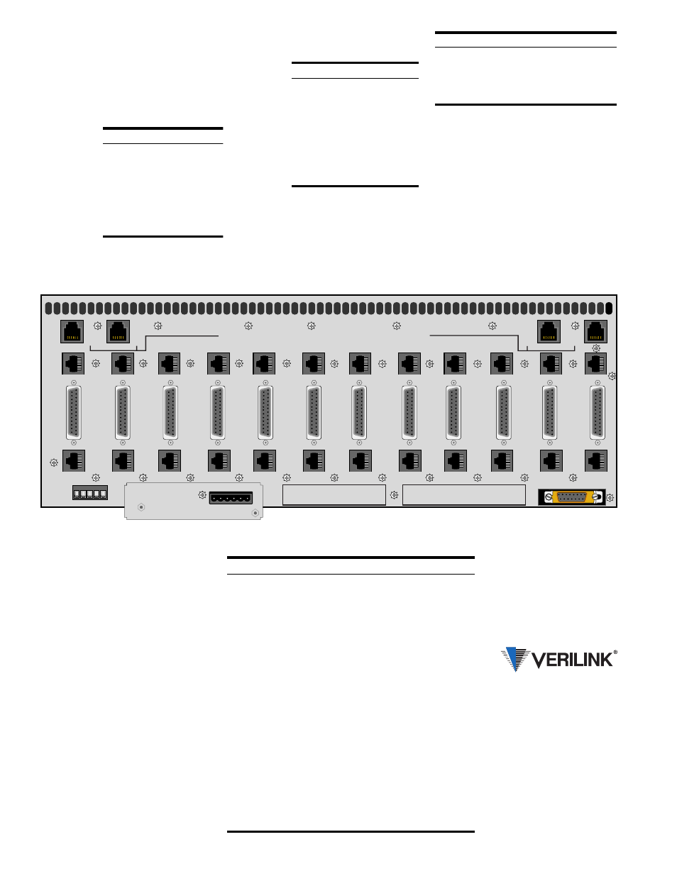
NMS Connections
The NMS ports are used to connect the chas-
sis into the 8100A Site Controller. Within the
chassis, each unit is physically connected to
the next unit in a daisy chain. Two 6-pin
modular connectors are provided for both the
A and B sides.
All units in the
chain must use
the same NMS
bit rate, how-
ever, each unit
in the NMS
chain must
have a unique
address.
Network and DTE
Connections
The T1 DTE
and T1 NET
ports are 8-
pin modular
jacks. The
maximum
suggested
cable lengths
for chassis
connection
to the net-
work are listed in the following table. These
distances are based on a temperature of 70°F,
0.083
µ
F/mile capacitance, a 27 dB loss, and
a 100
Ω
, non-loaded, twisted pair cable.
Alarm Connections
Alarm conditions from all modules in the
chassis are bused together in parallel and are
presented on a single set of alarm relay con-
tacts (TB1, pins 3 and 4) allowing connection
to a remote indicating device. All modules in
a common chassis must operate in the nor-
mally open (NO) mode.
Connections to the contacts should use 20-
gauge stranded wire (or similar). The contacts
are rated at 120 mA (AC or DC).
Pin
NMS In
NMS Out
1
Not Used
Not Used
2
Signal Gnd
Signal Gnd
3
Data Out
Data Out
4
Data In
Not Used
5
Signal Gnd
Signal Gnd
6
Not Used
Not Used
Pin
T1 DTE T1 NET
1
Data Out
Data In
2
Data Out
Data In
3
Not Used
Not Used
4
Data In
Data Out
5
Data In
Data Out
6
Not Used
Not Used
7, 8
Signal Gnd
Signal Gnd
Cable Type
Loss per 1000'
Max Length
26-gauge
6.8 dB
3,900 ft
24-gauge
5.4 dB
5,000 ft
22-gauge
4.2 dB
6,400 ft
19-gauge
3.0 dB
9,000 ft
External Clock
Connections
TB1 provides the contacts allowing connec-
tion to an external timing source (pins 1
and 2).
High-Speed DTE
Connections
The high-speed port connections use a
female 25- pin subminiature DB-25 connec-
tor. The pin interface comparisons are de-
tailed in the table on the right.
If the unit is connected to an EIA-530 DTE
type device, only a one-to- one DB-25 cable
is required.
If the unit is connected to an RS-449 com-
patible interface, an adapter cable must be
used to match the 37-pin RS-449 standard.
The V.35 option also requires an appropriate
adapter cable to connect to devices that use
the standard 34-pin V.35 interface.
Common Name
DB-25
EIA-530
RS-449
V.35
Frame Ground
1
1
1
A
Signal Ground
7
7
19
B
Transmit Data (A)
2
2
4
P
Transmit Data (B)
14
14
22
S
Receive Data (A)
3
3
6
R
Receive Data (B)
16
16
24
T
Request to Send (A)
4
4
7
C
Request to Send (B)
19
19
25
Clear to Send (A)
5
5
9
D
Clear to Send (B)
13
13
27
Data Set Ready (A)
6
6
11
E
Data Set Ready (B)
22
22
29
Data Term Ready (A)
20
20
12
H
Data Term Ready (B)
23
23
30
Data Carrier Detect (A)
8
8
13
F
Data Carrier Detect (B)
10
10
31
Transmit Clock (A)
15
15
5
Y
Transmit Clock (B)
12
12
23
AA
Receive Clock (A)
17
17
8
V
Receive Clock (B)
9
9
26
X
Terminal Timing (A)
24
24
17
U
Terminal Timing (B)
11
11
35
W
145 Baytech Drive
San Jose, California 95134
127 Jetplex Circle
Madison, Alabama 35758
(800) 837- 4546
www.verilink.com
FAX-On-Demand
(800) 957-5465
Technical Assistance Center
(800) 285- 2755