Connectors – Verilink 1051-1 Chassis (CG) Configuration/Installation Guide User Manual
Page 2
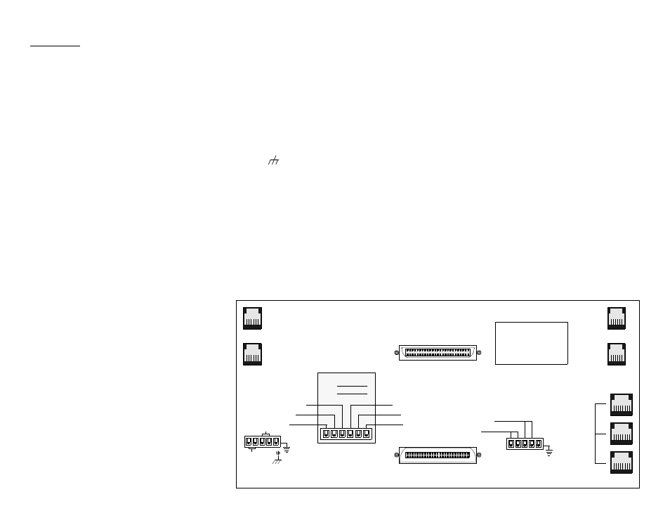
Model 1051-1 Chassis, Rear View
Connectors
Below is a description of the rear panel chassis connectors.
Refer to the reference manual of the particular module used
(2000, 2048, and/or 2100) for detailed information. Some
modules do not use all the connectors provided.
Equipment: The module’s equipment side interface is
referred to as a DSX interface. The equipment physical inter-
face is a standard RJ48H 50-pin connector.
Network: The module’s network side is referred to as the
network interface. The network physical interface is a stan-
dard RJ48H 50-pin connector.
NMS: The ‘NMS IN’ and ‘NMS OUT’ ports are used to con-
nect the modules in the chassis to the EM8000 element man-
ager. Within the chassis, each module is physically connected
to the other units in a daisy chain fashion. Two 6-pin modular
connectors are provided for each of the ‘A’ and ‘B’ sides.
When a network manager is not used, both NMS ports must
be connected to each other with the supplied NMS cable.
Each module in the NMS chain must use the same NMS bit
rate and have a unique address. Unit addresses do not corre-
spond to chassis slot numbers.
The ‘NMS OUT’ port is an output only connection used for
connecting multiple units together in a daisy chain in/out bus
arrangement. The network manager connects to the ‘IN/OUT’
port of the first unit in the chain. The ‘OUT’ port is used for
connection to the ‘IN/OUT’ port of the next unit. The last unit
in the chain connects its ‘OUT’ port to the ‘IN’ port of the
network manager.
The communications bus is automatically tied into each mod-
ule, allowing single point interfacing to the chassis. Cards
may be inserted and removed from the chassis without rewir-
ing the communications bus. Communications are restored via
the shorting contacts on the backplane when a slot is vacant.
External Clock: External contacts are provided (with a 5-pin
terminal strip) to permit connection to a remote clocking
source
Alarm Out: Alarm relay contacts are provided for connec-
tion to a remote indicating device. The two contacts labeled
‘Alarm Out’ are configured to operate either in a ‘normally
open’ or ‘normally closed’ mode, depending on the module’s
switch setting. All CSU modules in a common chassis must
use the same alarm relay mode. Make connections to the
alarm contacts using 20-gauge stranded wire (or similar).
Power: Power is received from an external supply (such as
the TxPORT 1040 Power Shelf) and distributed to each card
slot. All units are powered by - 48 VDC sources which are
connected to the 6-pin terminal strip. The chassis is designed
with two power buses. The ‘A’ bus feeds the odd slots (1, 3, 5,
7, 9, and 11). The ‘B’ bus feeds the even slots (2, 4, 6, 8, 10,
and 12).
Connect a ground lead (18 to 20-gauge) to the terminal
marked ‘
’ on the lower left corner. Connect the other end
of this lead to an appropriate facility ground.
Warning: Connect the ground lead before applying power to
the unit.
The chassis is shipped with a redundant power board installed
on the power connector. This board allows the chassis connec-
tion of two independent -48 VDC supplies operated in a
redundant mode. All slots in the chassis are powered from the
combined input of the A and B power supplies. If either sup-
ply fails, the other will power the entire chassis.
To operate in the redundant power mode, connect the A bus
terminals to the corresponding terminals of power supply A.
Connect the B bus terminals to the corresponding terminals of
power supply B.
When using a single power source, simply connect the A bus
terminals on the redundant power board to the corresponding
terminals of power supply A. This is the same as the redun-
dant configuration with supply B not operational.
When using a dual independent power supply, one -48 VDC
source feeds the A bus while another -48 VDC source feeds
the B bus. First, remove the redundant power board. Connect
the A bus terminals to the corresponding terminals of power
supply A (to power the odd numbered slots). Connect the B
bus terminals to the corresponding terminals of power supply
B (to power the even numbered slots).
Each module requires a certain amount of current. Ensure that
the proper fuse size is used. If using the 1040 Power Supply
Shelf, refer to the accompanying configuration guide.
ASSY 2000 - 053
Redundant
Power Board
Controller
Alarms
Controller
Ports
Minor Alarm
1051 Chassis
NETWORK
50
26
1
25
EQUIPMENT
25
1
26
50
J1
J2
REV
S / N
Clock
External
Alarm
Major Alarm
(B)
BUS
-48 VDC
Chassis Ground
-48 V Return
(B)
NMS
OUT
(B)
NMS
IN
Out
(A)
BUS
-48 VDC
Signal Ground
- 48 V Return
(not used)
(not used)
(not used)
1
2
3
(A)
NMS
OUT
(A)
NMS
IN