1041 power shelf rear panel, Rear panel description, Simplified schematic – Verilink 1041 (CG) Configuration/Installation Guide User Manual
Page 2
–
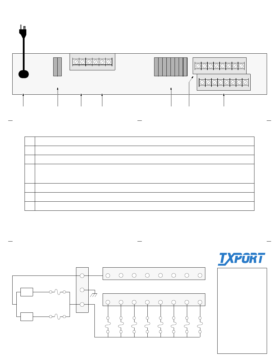
1041 Power Shelf Rear Panel
115 VAC
2.0 A
60 HZ
ALARM
CONTACTS
+
GND NC
C
NO
A
B
F1
FUSE RATING
3.0 A 125 V
1
2
3
4
5
6
7
8
F2
FUSE RATING
.25 A 125 V
48 VDC
2A
1
1
8 RETURN
8 -48 VDC
Rear Panel Description
1
AC Power Cord: This cord can be connected to any available 110 V outlet.
2
Fuse F1: Fuses A and B protect the main power feeds.
3
48 VDC: The three screw terminals on the left are used to connect a -48 VDC load to the main feeds.
4
Alarm Contacts: The three isolated contacts on the right permit connection to a remote indicating device. The contacts may be
configured as normally closed (NC) or normally open (NO). NO and NC refer to the contact’s relationship to the common (C)
contact under a ‘no alarms’ condition.
5
Fuse F2: Fuses 1 through 8 protect the multiple load terminal strip with a rating of 0.25 A each.
6
- 48 VDC: These 8 screw terminals are used to connect multiple 0.25 A loads to the main feeds.
7
Return: These 8 screw terminals are used as returns for the multiple feeds.
2
4
5
6
Simplified Schematic
P/S A
P/S B
-48 V
-48 V
F1-A
3 A
F1-B
3 A
F2
1
F2
2
F2
3
F2
4
F2
5
F2
6
F2
7
F2
8
2
1
3
4
5
6
7
8
2
1
3
4
5
6
7
8
RETURN
-48 VDC
+
–
•
•
3
1
7
GND
8 fuses at 0.25 A each
TxPORT Customer Service
127 Jetplex Circle
Madison, Alabama 35758
Customer Service Returns:
800- 926-0085, ext. 227
Product Technical Sup-
port:
(8 – 5 Central Time)
800-285- 2755 or
205-772-3770
Emergency After Hours:
800-285-2755
E-Mail (Internet Address):
T
R
A
N
S
P
O
R
T
®