Gas or electric heat, Sample wiring diagrams, Page 12 – Venstar T1100REC User Manual
Page 13
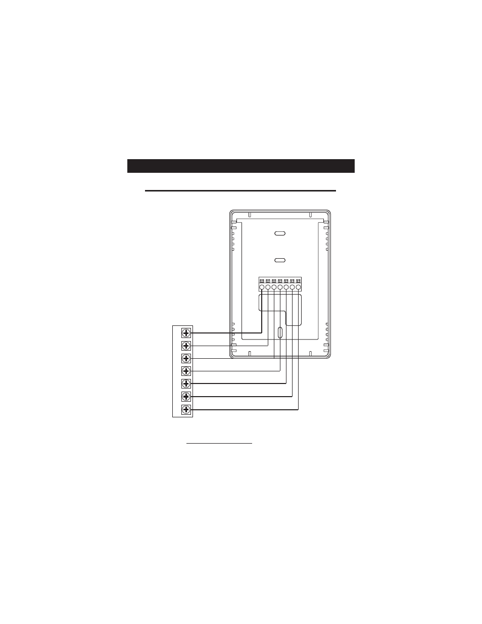
Sample Wiring Diagrams
W2
Y2
R
O
W1
B
Y1
G
C
* If using first stage electric heat, the “EH” dip switch must be
set to ON (see page 5).
** If using a
, the “HP” dip switch must be
set to OFF (see page 5).
Commercial heat pump
Gas or Electric Heat
POWER
R
COMPRESSOR
Y
W
GAS VALVE
or
STRIP HEAT
COMMON
C
FAN
G
2nd STAGE
COOLING
Y
2
2nd STAGE
HEATING
W
2
Commercial Gas or Electric Heat*,
Electric Cool, split systems & package units
including Commercial Heat Pumps.**
7 Wire, 2 Stage Cooling, 2 Stage Heat
Page 12