Lowel stand accessorie s instructions – Tiffen Stands User Manual
Page 2
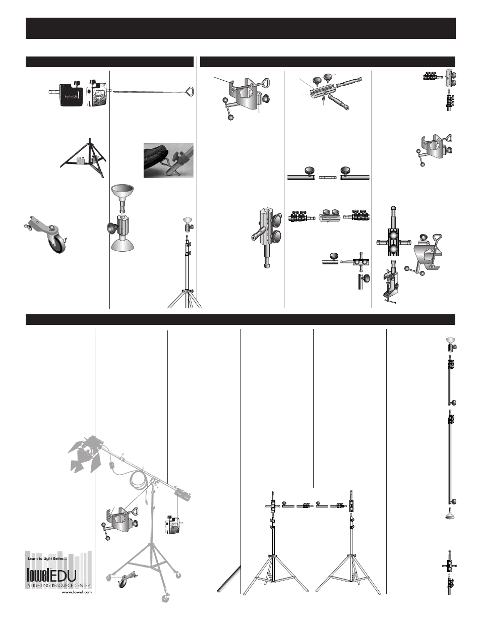
The following booms are
assembled from components
described on this sheet. The
same components can be used
individually and in other com-
binations, as required. The
equipment may also be
extended or adapted using
additional Lowel components
(see "Stands, Poles, Booms,
Rigs" sections at lowel.com or
in Lowel Catalog). Also, see
"Warnings" on front page.
Tighten all knobs
adequately with
hand leverage only.
Never raise stand or
adjust boom while
people are under it.
Floor-to-
Ceiling Pole
1 Assemble required
number of poles H
and/or half poles I
to reach vertical span.
2 Lock on ceiling link
F and G at opposite
ends.
3 To hold securely,
cups on ceiling link
must be flattened
completely against
floor and ceiling.
This is most easily
done by pressing
down with a foot
while extending
a pole section with
one hand and locking
collar clamp on
pole with the
other hand.
Lights that are not too
heavy can be attached
with suitable clamps
such as the Tota-clamp.
4 An Interlink J
inserted between pole
and top ceiling link
can also support
a light.
Caution: Test for safety of
installation and never
use poles horizontally.
3 If seamless paper is to be
used, insert pole or two
interlocked poles C and
D (or pipes if preferred)
through roll. (Some
small diameter cardboard
tubes may necessitate
substituting 1/4-20 bolts
for knobs on poles.)
4 Lock poles to Interlinks.
Elevate both stands
simultaneously,
if possible.
Other materials suitable for
background or blocking or
diffusing light may be
clamped or taped to poles.
Lights may be mounted to
studs projecting from
Interlinks and will be well
positioned for backlight
sources.
Lowel Anchors
Code: LA (Set of 4)
Ground spikes fit through leg holes
in KS, KSA and Grand stands to
increase stability when used on
grass, sand etc. and are recommend-
ed especially when reflectors are
used. A hand, foot or rock can be
used to force
the Anchor
through the
holes in the
legs and into
the ground.
Ceiling Link
Code: KCL
Set includes one male A,
one female B.
Holds one or more
lights with Lowel
Clamps and Grips.
The female half
of the set can be
attached to a stand to secure
it against a ceiling.
Rubber and aluminum compo-
nents lock onto ends of Lowel
poles. Compression secures
rig in place to make floor
to ceiling poles.
Lowel Stand Accessorie s Instructions
Lowel Weight
Code:
LW
Weight: 4.25
lbs (1.93 kg)
Modular counterweight. A 5/8" (1.59
cm) stud locks on female end of
Lowel poles to counterbalance
booms. Two or
three weights
fit together.
For additional
ballast, tighten
knob securely
to hold weights together. Slots in
bottom fit on stand leg struts to
increase stability.
Lowel Casters (3)
Code: LC
Weight:
2.4 lbs (1.09 kg)
Lockable wheels
fit leg holes on
KS, KSA and Grand Stands.
Especially helpful for booms and stu-
dio lighting. (Set of 3). Unscrew
wing-nut bolt, place stud thru leg
hole, attach wing-nut & tighten.
Stand Accessories
Interlink System
B
B
A
Booms, Supports & Rigs
A
C
D
B
B
F
I
H
G
J
Basic Boom
Code: SP-91
1 KSA Stand (KSA)
1 Grip (KG)
1 Full Pole (KP)
2 Lowel Weights (LW)
1 Set (3) Lowel Casters (LC)
1 Pkg (10) Cable Clips (K4CC)
Big Boom
Code: SP-90
1 Grand Stand (GS)
1 Grip (KG)
1 Full Pole (KP)
2 Lowel Weights (LW)
1 Set (3) Lowel Casters (LC)
1 Pkg (10) Cable Clips (K4CC)
Putting together
a Boom
1 Assemble casters A to
stand B through holes in
end of legs and tighten
wing nuts.
3 Lock Grip D onto stud and
lock tilt control D1,
at convenient angle, using
knob with balls on ends.
4 Extend pole E half way;
insert it into V portion of
Grip D2; cradle and tighten
lock knob.
5 Lock one weight F into
female end of pole.
6 Lock light or other
equipment onto 5/8” male
stud on boom.
7 Lock in second weight.
8 Adjust for balance using
extension on pole
or move entire Pole
within Grip.
Background
Support
Code: SP-93
2 KS Stands (KS)
2 Interlinks (K1-10)
2 Full Poles (KP)
This versatile rig supports
seamless paper rolls, black
velour, other material, adjusts
from 32" (81.3 cm) to 10’
(3.05 m) wide. Accepts two
back lights without additional
clamps; components can be
used separately as well.
1 Attach Interlink A to one
stand, Interlink B to other
stand.
2 Remove cross stud from
Interlink B by loosening
retaining bolt with 7/16"
wrench or Vise-grip.
Lowel Grip
Code: KG
This versatile clamp attaches to
stands, poles, pipes, 2" x 4"s etc. to
support lights with Interlink; makes a
boom out of Stand and Pole; works
with Space-clamp, Maxa-mount,
Frame-up. Tilts 180°; pans 360° and
locks securely.
Lowel Interlink
Code: K1-10
Interconnects various
Lowel components. Adds
multiple mounting posi-
tions; joins two Lowel
Poles (male or female
ends) in a straight line or at
right angles (90°). Both 5/8"
(16mm) studs are removable
and have a 1/4-20 threaded
hole to simplify mounting acces-
sories with 1/4-20 bolts.
The three main parts of the
Interlink can be used together
or separately.
The following are a few of the vari-
ous Interlink combinations.
Stud can connect the female ends
of two Lowel Poles (or other
components).
Body can interlock two male ends of
Lowel Poles (or other components
such as clamps).
Full Interlink
can connect the
female ends of Lowel
Poles (or other components)
at 90° (right) angle.
Body can connect
the male end of
Poles, or a Stand and Pole, to
form a 90° (right) angle.
Interlink or just the stud
can be locked into the 5/8" female
connection on a Lowel Grip and the
assembly can then be clamped onto
any part of any
stand, pipe, 2x4 etc.
A light or another
Grip can be
attached to the stud.
Interlink can be locked onto a Tota-
clamp A, Lowel Grip B, or various
accessories.
V groove
Locking knob
Stand fitting
Tilt control
Body
Identical studs
Use 7/16' wrench
1/4-20
threaded
hole
A
B
Cross
hole
E
F
A
D
D1
D2