Harvestman 1986 zorlon cannon mark II User Manual
Harvestman Audio
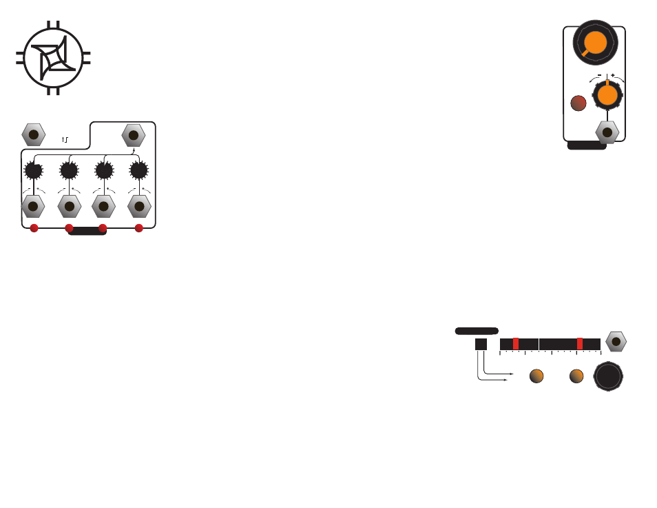
CV
RANGE
A FREQ
0-5V
Manual control of internal clock frequency.
CV attenuverter for internal clock frequency.
Clock mode: Red = low, Orange = normal, Green = double. Double
mode reacts to BOTH rising and falling edges when used with external
clock.
CV input for internal clock frequency.
0-5V
EXT CLKIN A
MIX OUT
A OUTS
0-5V
Mix output.
Attenuverting mixer. Center position mutes channel at mix output. Turning clockwise adds the
corresponding channel to the mix. Turning counterclockwise subtracts it. On the A mixer, the mixer
adds to only one "side" of the mix waveform. On the B mixer, it adds to both.
Individual output for channel. The A outputs are optimized for gate generation, while the B outputs
are designed for audio signals.
External clock input. Disables internal clock controls when used.
SHIFT REGISTER TIPS:
If a tap configuration is "maximal", then it is the longest possible sequence for that number of bits. For example, an 8-bit maximal LFSR has 255 states, a 7-bit has 127state, a 6-bit has
63 states, and so on.
Shorter maximal shift register lengths have a higher "pitch", as they divide the input clock by a smaller number.
All configurations with an odd number of taps are non-maximal.
Non-maximal sequences are divided into a number of different sequence lengths, selectable at random by pulsing the "SEED" input. The seed input will update all eight outputs Try
creating rhythmic shifts of timbre or sequence by creating a mix of several non-maximal registers, and then sending gates to the Seed input.
A table of maximal shift register configurations is given below. All of these are available onboard the Zorlon Cannon.
BITS `````MAXIMAL TAP CONFIG
3
3, 2
4
4, 3
5
5, 3
6
6, 5
7
7, 6
8
8, 6, 5, 4
9
9, 5
10
10, 7
11
11, 9
12
12, 11, 10, 4
13
13, 12, 11, 8
14
14, 13, 12, 2
15
15. 14
16
16, 14, 13, 11
The eight outputs can each have a different configuration. To edit, hold down the "output select" button and turn the rotary
encoder until the desired output is illuminated with a GREEN LED. Now, release the output select button.
Each jack represents the output of a shift register. Turn the encoder to define the length of the register which is visually
represented on the display. Then, you can press the "tap/length" button and continue turning the encoder to select the
feedback tap configuration. These parameters determine the "period" of the pseudorandom sequences.
When you have edited the outputs to your satisfaction, you may store them to memory by pressing down on the rotary
encoder knob for 2 seconds. The "range" buttons will blink once to confirm this storage. To reload the stored preset, double-
tap the encoder knob quickly without holding it down.
More information and media samples:
http://www.theharvestman.org/1986mk2.php
Support:
email [email protected]
SEED
0-5V
DOUBLE-Press Encoder to load preset.
Hold encoder to save.
(PUSH DOWN
AND TURN)
TAP/
LENGTH
OUTPUT
SELECT
EDIT FACILITY
16
12
8
4
EDIT FACILITY