Specifi cations, Connections (input and output xlr-3), Connections (headset and – Teac KS-4320 User Manual
Page 15: Connectors), Moni/tb
15
TM
Specifi cations
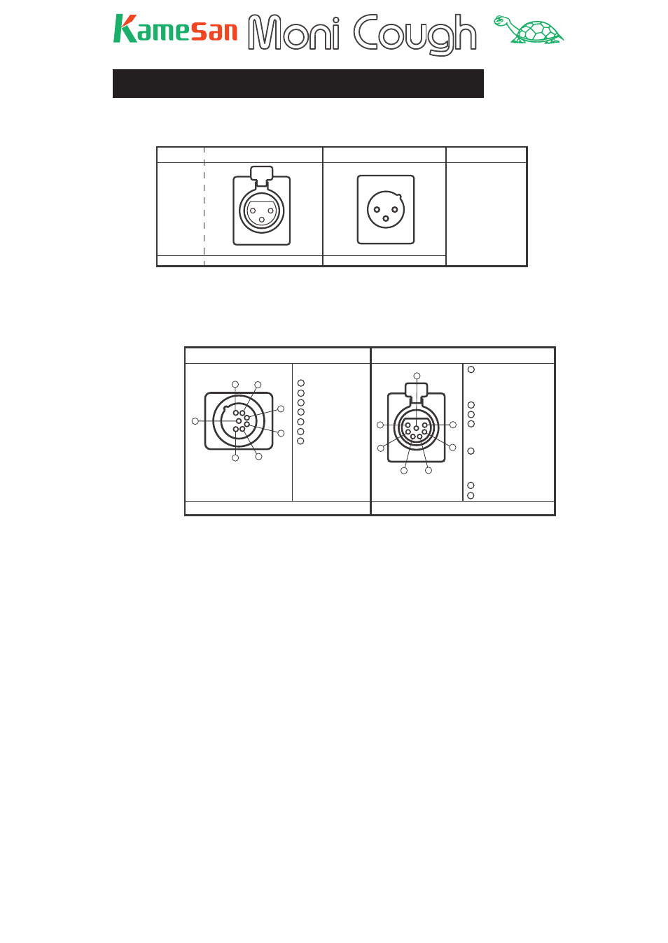
Connections (input and output XLR-3)
INPUT
¥connector
¥¥OUTPUT connector
Pinout
ł Type
¥¥XLR - 3 - 31 ¥¥¥¥¥ XLR - 3 - 32
Plug type
XLR - 3 - 12 type XLR - 3 - 11 type
1
3
2
1
2
3
2
¥HOT
3
¥COLD
1
¥GROUND
Connections (headset and
MONI/TB
connectors)
HEADSET Connector
¥¥Pinout¥¥¥¥ ¥¥MONI / TB Connector¥¥Pinout
NC7MDL-B-1
¥¥¥¥¥¥¥¥¥¥¥¥¥¥¥¥XLR - 7 - 31
Plug type
¥¥¥¥XLR - 7 - 1 1 type¥¥¥¥¥¥¥¥¥¥¥¥¥¥¥XLR - 7 - 12 type
MIC IN ( HOT )
F.G
MIC IN ( COLD )
H.P - Left ( HOT )
4
3
2
1
5
6
7
H.P - Left ( COLD )
H.P - Right ( HOT )
H.P - Right ( COLD )
5
6
7
4
3
2
1
TALK BACK OUT ( HOT )
F.G
RTS *
(GROUND )
Clear-com 2 ** (GROUND )
Clear-com 1 ***
(GROUND )
TALK BACK OUT ( COLD )
MONI INPUT - L ( HOT ) or
RTS INTERRUPT * or
Clear-com 2-A **
4
3
2
1
5
6
7
MONI INPUT - L ( COLD ) or
RTS NON-INTERRUPT * or
Clear-com 2-B ** or
Clear-com 1 ***
MONI INPUT - R ( HOT )
MONI INPUT - R ( COLD )
5
6
7
4
3
2
1
Note that the MONI/TB connector pinout varies, depending on
the setting of the monitor switch.
In the table above, no asterisk by a pin descriptor means that
the pin retains its function in all modes or that in the case of
multiple functions for that pin, the LINE mode is selected. One
asterisk (*) indicates the RTS setting. Two asterisks (**) show
that this assignment is valid in the CC-2 mode, and three aster-
isks show the assignment is valid in CC-1 mode.