Figure 7. wall plate controller wiring, Figure 6. wall plate controller – SVS PLASMA ONE 4 User Manual
Page 11
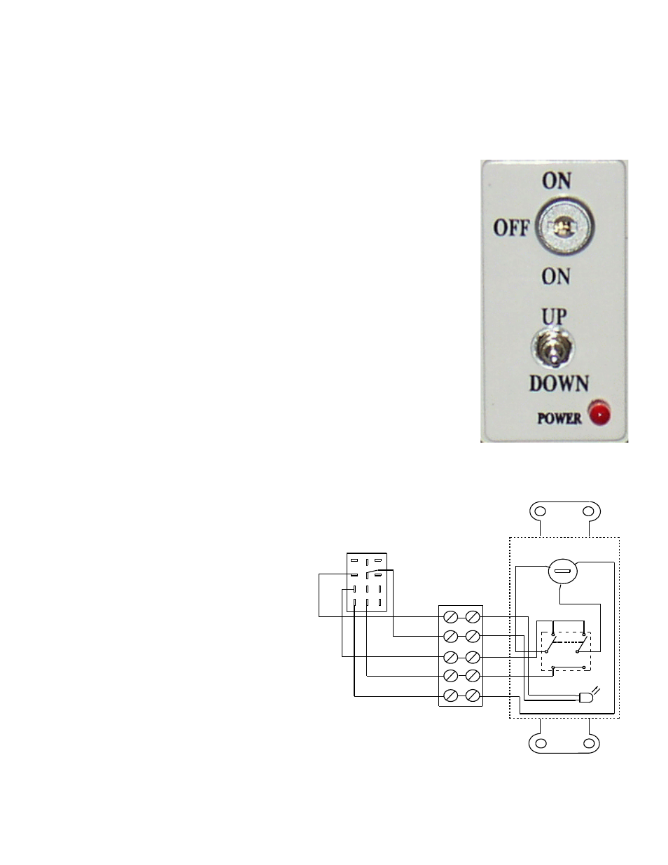
a. How to use the Wall Plate Controller
1. To lower the Lift, turn the key switch to the ON position and press the toggle switch down. The Lift will
lower as long as you hold the toggle switch down, the Lift will stop when it reaches the full down
position and compresses the Down Limit microswitch.
2. To raise the lift, urn the key switch to the ON position and press the toggle switch up. The Lift will rise
until the Up Limit microswitches are compressed. The Lift will rise as long as you hold the toggle
switch up.
3. The Off position on the key switch disables the Lift.
4. The Power light on the Wall Plate Controller only comes on when the
Lift is raising or lowering (Lift motor turning), not when power is
applied to the Lift.
Important: The toggles switch on the Wall Plate Controller must be pressed to
raise or lower the Lift, releasing the toggle switch stops the Lift. This is designed
as a safety feature. The key switch is an extra precaution, when the key is
removed, the Lift is secure.
b. Connecting a Touch Screen Controller (External Controller)
The simplest external controller connections are to use the White wire (pin 1) as
the common and the Green wire (pin 4) for down and the Red wire (pin 2) for
up. See Figure 9. Also:
1. Program a release of relays to stop the Lift on up and down positions
2. Program a time out after the normal runtime, 2 seconds max.
3. Program an exclusive lockout on up and down so that both cannot be
activated at the same time. (Note: SVS Lifts have a lockout function that
disables the Lift when it receives a up and down command at the same
time. Removing one of the two commands
releases the lockout condition.)
4. Hold relays on to raise/lower the Lift.
5. Never leave voltage on the up and down.
Always program a release after the travel
time has been achieved.
If you have any questions please contact SVS for
proper wiring.
9. ACCESSORY INSTALLATION
Please refer to the accessory installation
instructions located in the accessory shipping
crates for specific instructions for each accessory.
The Accessory PPS-1 Plenum Shroud require that
hardware be added to the threaded rods
supporting the Lift before the Lift is installed.
SVS Plasma One 4 Lift Installation Instructions
Page 11 of 16
Figure 7. Wall Plate Controller Wiring
VIEW FROM BACK
(24vac)
+
-
(ON)
C
2
1
GRN
GRN
RED
UP
BLK
WHT
ORN
BLK
WHT
M OT OR
POWER ON
WHT
DOWN
ON-OFF-ON
RP2
(ON)
BLK
ORN
GRN
GRN
RED
WHT
3
2
1
4
5
6
9
8
7
12
11
10
Figure 6. Wall Plate
Controller