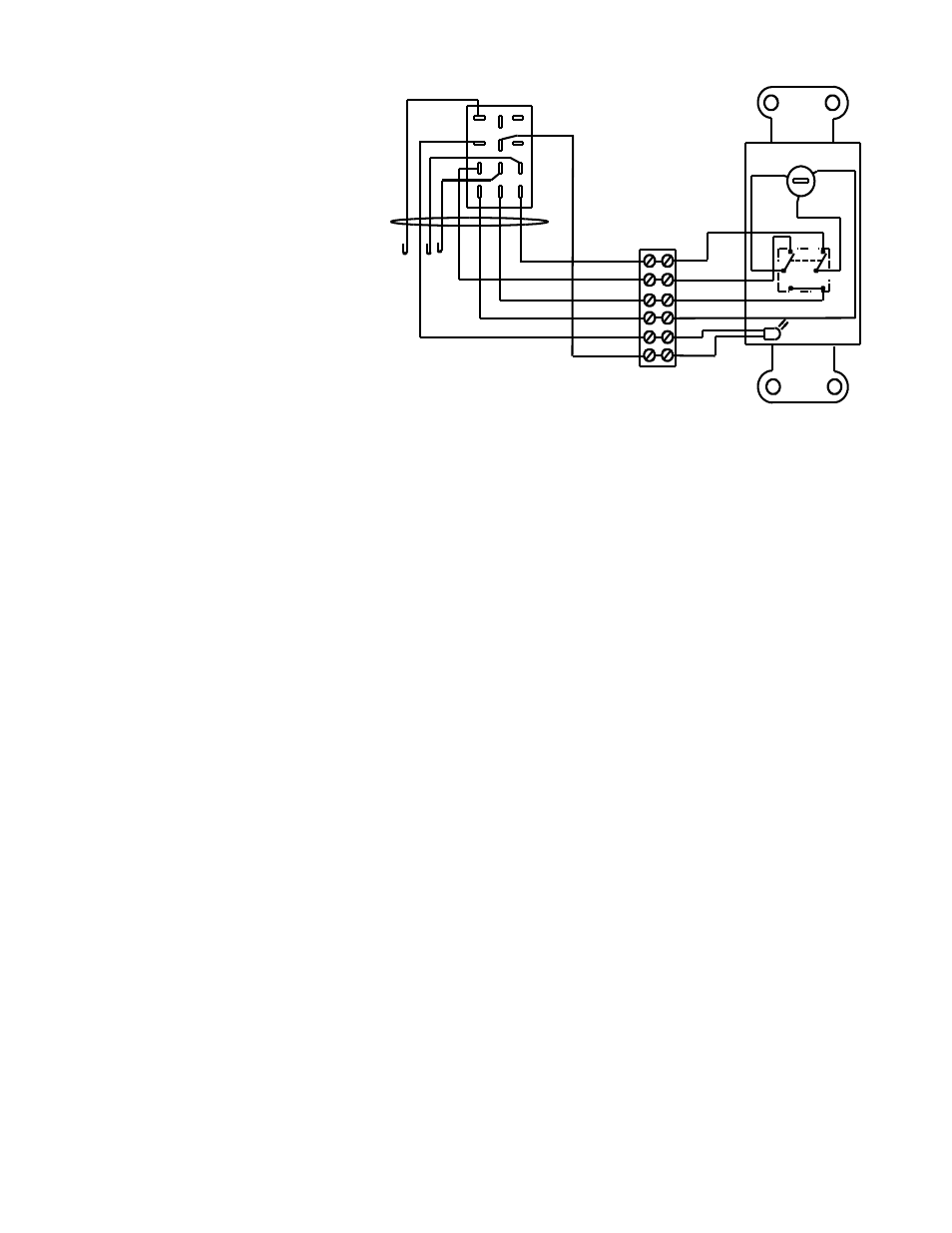
Wall plate controller, Rp2 (connects to rj2), Figure 8. wall plate controller wiring – SVS TL1 110V User Manual
Page 11
b. Connecting a Touch Screen
Controller (External Controller)
The simplest external controller
connections are to use the White wire as
the common, the Brown wire for down to
Show position and the Red wire for up.
For this and other wiring options please
refer to the external controller wiring
diagrams in the Appendix. Also:
1. Program a release of relays to
stop the Lift on up and down
positions
2. Program a time out after the
normal runtime, 2 seconds max.
(SVS Lifts raise/lower at 1-
inch/second.)
3. Program an exclusive lockout on
up and down so that both cannot be activated at the same time. (Note: SVS Lifts have a lockout function
that disables the Lift when it receives a up and down command at the same time. Removing one of the
two commands resets the lockout.)
4. Hold relays on to raise/lower the Lift.
5. Never leave voltage on the up and down. Always program a release after the travel time has been
achieved.
If you have any questions, please contact SVS for proper wiring.
9. ACCESSORY INSTALLATION
Please refer to the accessory installation instructions located in the accessory shipping crates for specific
instructions for each accessory. The Accessory #2 Plenum Shroud and Accessory #12 Decorative Cover require
hardware be added to the threaded rods supporting the Lift before it is installed. The Accessory #1 Ceiling
Closure and FP1 Closure Panel attach the bottom Frame of the Lift using supplied threaded rods.
10. MOUNTING THE PROJECTOR
After checking the Lift operation and all clearances you can install the projector on the Lift. The projector can
be installed using a ceiling type projector mount (inverted) or using an Accessory #13 Metal Platform (non-
inverted). For custom mounting option please contact SVS, Inc.
•
The Projector can be attached to the Lift using an Accessory #9 Projector Mount from SVS or a standard
ceiling type projector mount. The projector mount is required to attach the projector to the Lift. The base
box of the projector mount will need to be bolted to the Lift. The mount should be centered side-to-side
with the Lift Frame. See Figure 9.
•
If a ceiling type projector mount is not available for the projector or if the projector needs to be non-
inverted, the projector can be placed on an Accessory #13 Metal Platform. The Accessory #13 Metal
Platform is a shelf mounted below the Lift to support the projector.
•
All weight attached to the lift must be centered between the lift's cables. The balance point of the
projector should be placed in line with the lift cables (+/- 1-inch). If this is not possible you may need to
counter weight the lift.
SVS TL1 Lift Installation Instructions
Page 11 of 16
Figure 8. Wall Plate Controller Wiring
VIEW FROM BACK
(24vac)
+
-
(SERVICE)
C
2
1
GRN BRN
UP
PUR
BLK
BLU
WHT
MOTOR
POWER ON
WHT
DOWN
SHOW-OFF-SERVICE
RP2 (CONNECTS TO RJ2)
YEL
(SHOW)
RED
WHT
ORN
BLK
GRN
RED
WHT
BLK
ORN
GRN
BRN
BRN
3
2
1
4
5
6
9
8
7
12
11
10
WALL PLATE CONTROLLER