Sundance SMT8090-365 User Manual
Page 9
Version 1.2
Page 9 of 12
SMT8090 User Manual
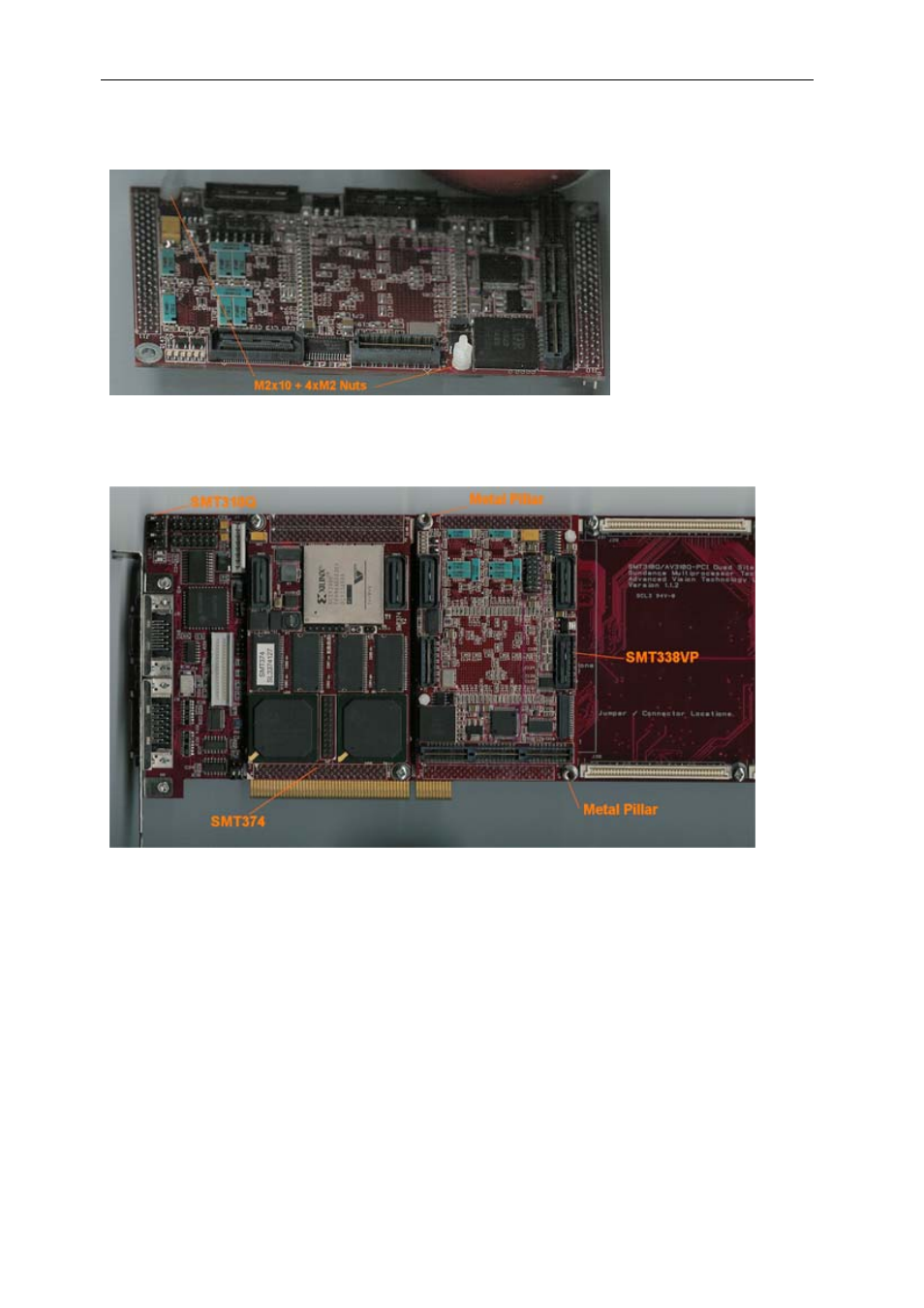
b – Then fit four M2 nuts on each screw.
c – Place the SMT338 on the second site (SMT365 already on first site) on the
SMT310Q and fit two metal pillars (3.3 Volts).
d – Place the SMT390 on top of the SMT338-VP. Make sure that both
modules fit firmly.
e – Fit two M2 nuts on the Nylon screws and two M3x4 screws in the 3.3V pillars.
3 – Connect CommPort 0 of the SMT365 to CommPort 3 of the SMT390 (T1C0 to
T2C3) via an FMS cable at the back of the SMT310Q.
4 – Connect SHBA on the SMT365 to SHBA on the SMT390-VP via the SMT516
(SHB to SHB PCB).
See also other documents in the category Sundance Equipment:
- SMT107 (16 pages)
- SMT6035 v.2.2 (39 pages)
- SMT6012 v.4.6 (22 pages)
- FC100 (12 pages)
- FC108 v.1.1 (10 pages)
- SMT6065 v.4.0 (45 pages)
- FFT v.2.1 (19 pages)
- SMT111 (18 pages)
- SMT118LT (10 pages)
- SMT118 (20 pages)
- SMT123-SHB (13 pages)
- SMT128 (15 pages)
- SMT145 (18 pages)
- SMT148 (35 pages)
- SMT130 v.1.0 (46 pages)
- SMT148FX (48 pages)
- SMT310Q (55 pages)
- PARS (70 pages)
- SMT166-FMC (52 pages)
- SMT166 (44 pages)
- SMT300Q v.1.6 (61 pages)
- SMT310 v.1.6 (50 pages)
- SMT317 (24 pages)
- SMT326v2 (24 pages)
- SMT338 (19 pages)
- SMT349 (32 pages)
- SMT339 v.1.3 (27 pages)
- SMT338-VP (22 pages)
- SMT358 (25 pages)
- SMT351T (37 pages)
- SMT351 (25 pages)
- SMT350 (45 pages)
- SMT362 (30 pages)
- SMT365G (23 pages)
- SMT364 (37 pages)
- SMT373 (15 pages)
- SMT368 (24 pages)
- SMT370v3 (46 pages)
- SMT377 (22 pages)
- SMT381 2007 (31 pages)
- SMT381-VP (81 pages)
- SMT387 (42 pages)
- SMT391 (18 pages)
- SMT384 (47 pages)
- SMT390-VP (55 pages)