Architecture – Sundance SMT8036 User Manual
Page 6
Version 1.4
Page 6 of 10
SMT8036 User Manual
are loop onto the ADCs inputs. The DSP grabs data from both channels and stores
them into a file, which can be read by a Matlab application for data displaying and
FFT processing. Sampling clocks (100MHz for the ADCs and 160MHz for the DAC)
are generated by on-board clock synthesizers.
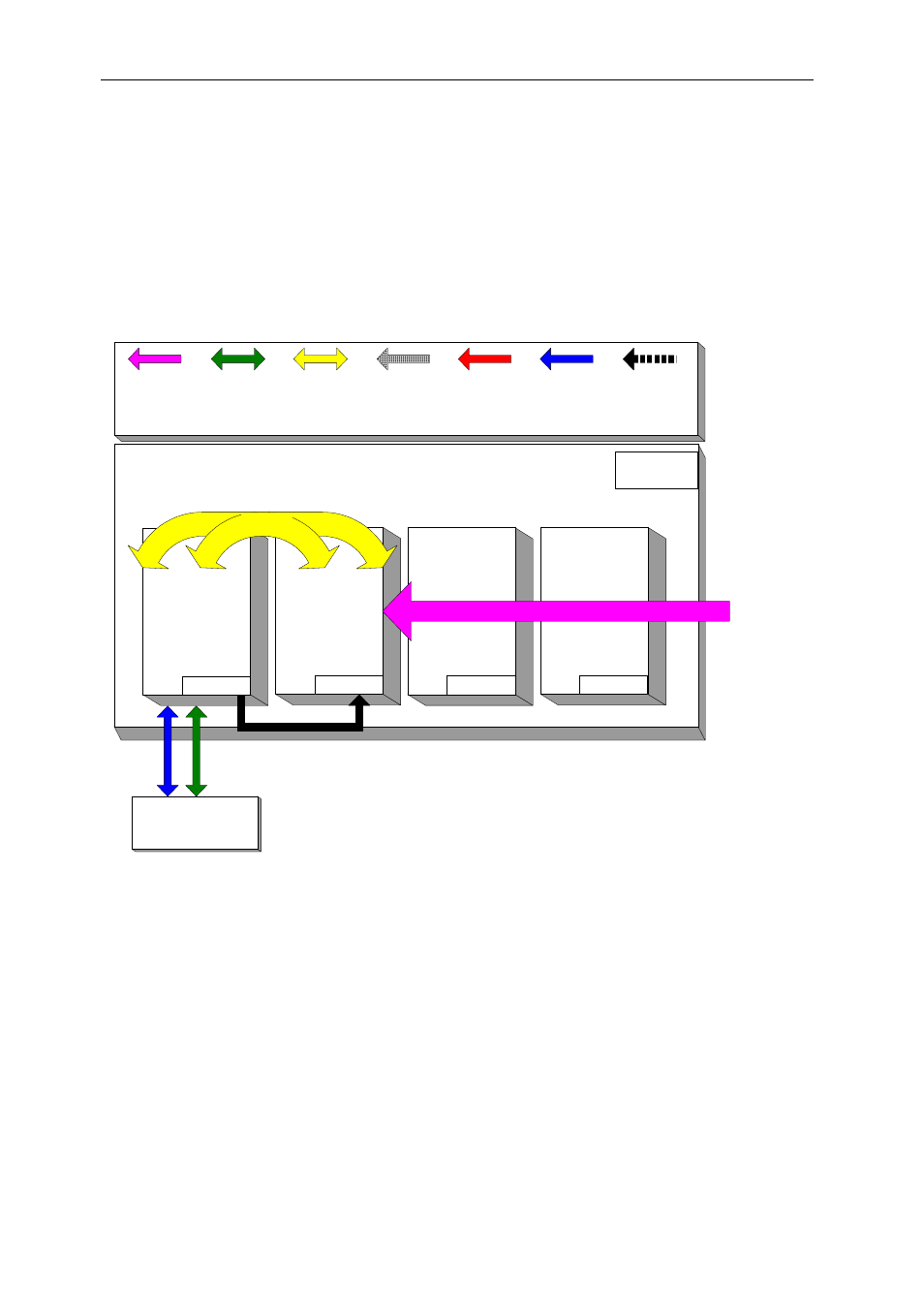
Architecture.
The following diagram shows the architecture of the SMT8036 system:
SMT370
DAQ
Module #2
Spare
SMT310Q
PC
Host
Data
SDB
Connection
Control
Comm
Port
Data
Comm
Port
Analogue
Connection
Processing
TIM site 2
TIM site 4
Data
SHB
Connection
Data
Global Bus
Connection
Spare
TIM site 3
SMT365
DSP Module
Module #1
TIM site 1
SMT506-BNC - MMBX to BNC cables
for analogue inputs/outputs and external clocks/triggers
SMT596
This manual is related to the following products: