3 module adjustments, 1 phase adjustment, Module adjustments – Sundance SMT399-F User Manual
Page 7
4.3 Module Adjustments
Several trimmer capacitors and multi-turn potentiometers are provided. The
following table describes their use;
Adjustment Function
VC1
Phase adjust COARSE.
VC2
Phase adjust FINE.
VC3
Output tuning COARSE.
VC4
Output tuning FINE.
R13
VGA gain adjust.
R4
OCXO frequency trim.
4.3.1 Phase Adjustment
When using an external clock input, the phase relationship between the input and
output can be adjusted. This is implemented using the LC tuned circuit consisting
of L1 and VC1&2.
Set VC1 and VC2 to their centre positions. Whilst monitoring the input and an
output on an oscilloscope, adjust VC1 for the correct phase delay. VC2 may be used
to make fine adjustments.
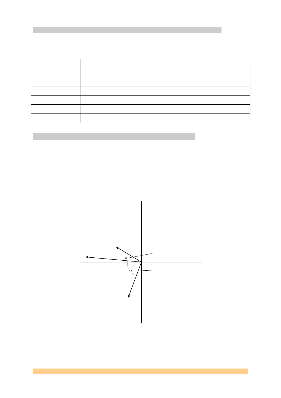
The diagram below shows a typical input-output phase relationship.
0
+90
-90
180
125mVp-p
+155°
310mVp-p
+177°
190mVp-p
-105°
SMT399-F
Input to Output phase delay.
Input: 100MHz, +7dBm
78° range using input tuned
circuit only, VC1
22° range extension using
output tuned circuit too, VC3
SMT399-F Clock Distribution Module User Manual
Page 7 of 11